
1. Why SPD standards are needed
A surge protective device limits transient overvoltages and diverts surge current. SPDs use nonlinear elements, most commonly metal-oxide varistors (MOVs), sometimes combined with fast-response elements of another type.
Standards allow SPDs to be compared objectively. They specify test impulses, application classes, residual voltage parameters, permissible operating conditions, safe disconnection requirements and status indication.
2. Two approaches: IEC/EN cascade protection and industrial SPDs to UL/IEEE
European practice often uses a multi-stage system, with separate SPDs at the incoming supply, in distribution switchboards and near sensitive equipment. This follows the zonal approach and test Classes I / II / III.
The US approach based on UL 1449 and IEEE C62.41 / C62.45 emphasises characterising the actual surge environment and testing a complete SPD as an industrial product. The central principle is to handle the main surge energy at the incoming supply or power switchboard and reduce residual overvoltages to a level safe for control equipment.
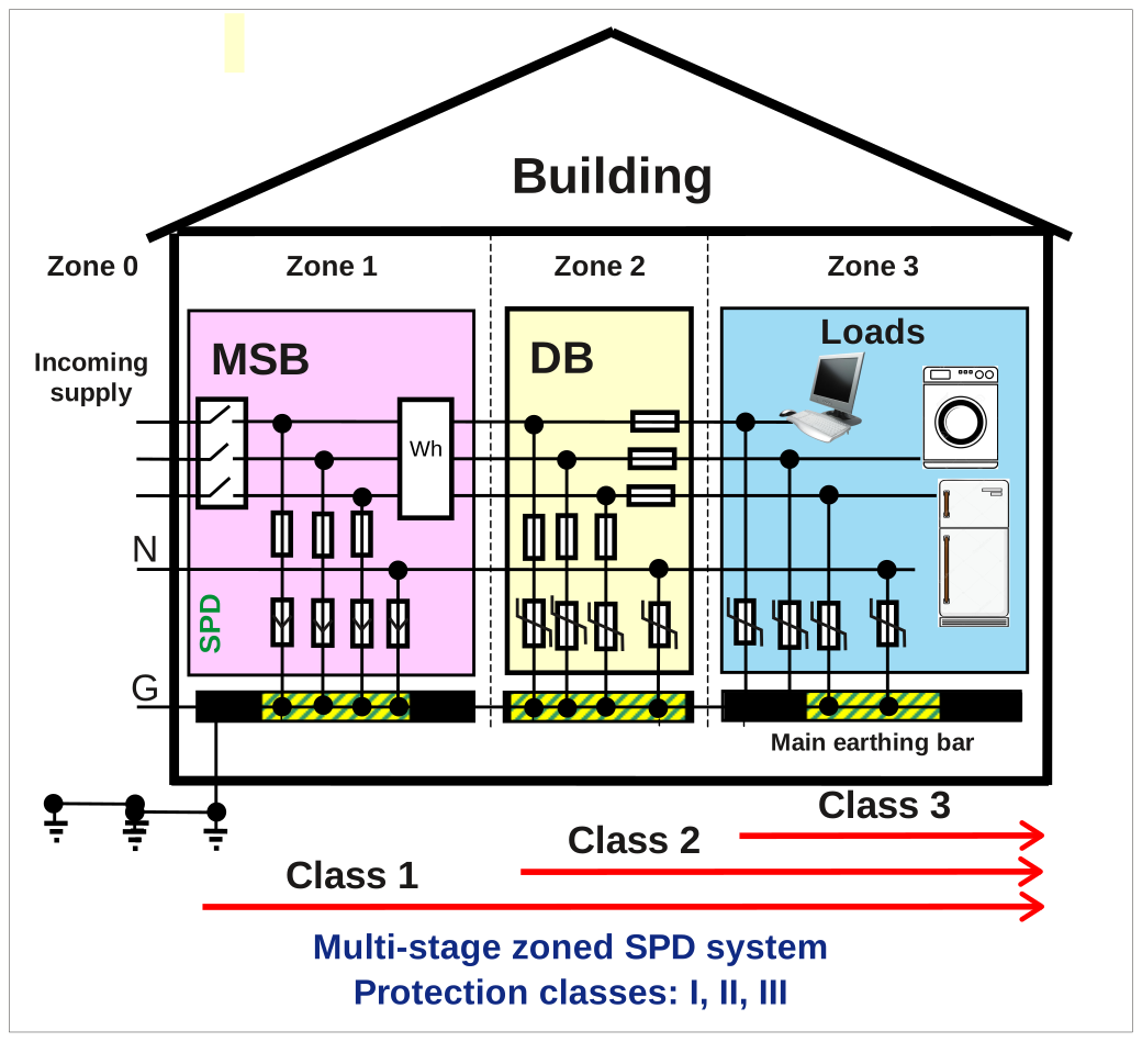
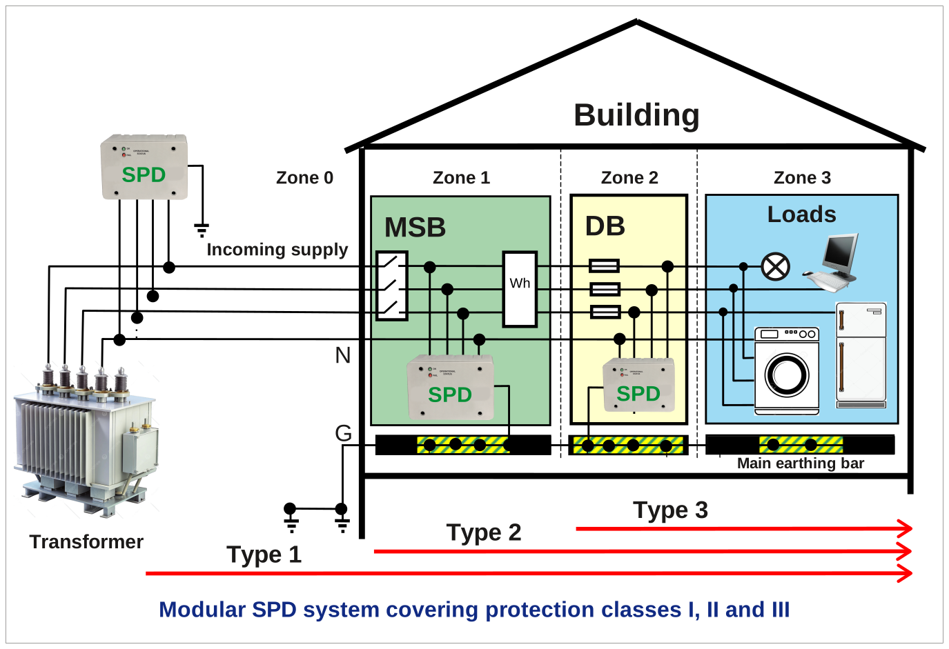
3. Classes and installation locations
| Protection level | Typical installation location | Function |
|---|---|---|
| Type 1 / Class I | Main incoming supply, main distribution switchboard or main LV switchboard, at the external supply entry point | Handles part of the energy from a lightning surge or a severe external surge; testing is associated with the 10/350 μs waveform. |
| Type 2 / Class II | Distribution switchboards, ATS equipment and standby power switchboards | Limits residual overvoltages after the first stage and surges originating within the facility; the typical impulse is 8/20 μs. |
| Type 3 / Class III | Directly adjacent to sensitive equipment, controllers, communications equipment and power supplies | Reduces residual overvoltage to a level safe for electronics; a combination wave is used. |
4. Main SPD selection parameters
Application location
Outdoor and indoor installations may have different requirements for enclosure construction, temperature, ingress protection and maintenance.
Response time
Indicates how quickly the SPD enters its voltage-limiting state. This is a critical parameter for sensitive electronics.
Surge current
Indicates the magnitude of surge current that the device can conduct without losing functionality under the declared test conditions.
Protection level
The kA rating is not the only consideration: the residual voltage experienced by the equipment after SPD operation also matters.
Uc and TOV
The maximum continuous operating voltage and temporary overvoltage withstand performance determine whether the SPD will degrade unnecessarily or undergo an emergency disconnection.
Status monitoring
Indication, volt-free contacts, a surge counter or remote signalling show not only that an SPD is present, but whether it is actually ready to provide protection.
5. MOV, SAD/MOV and hybrid solutions
In most industrial SPDs, the primary element is a metal-oxide varistor (MOV). It has a high resistance under normal conditions, but its resistance drops sharply during a voltage surge, allowing it to divert the surge current.
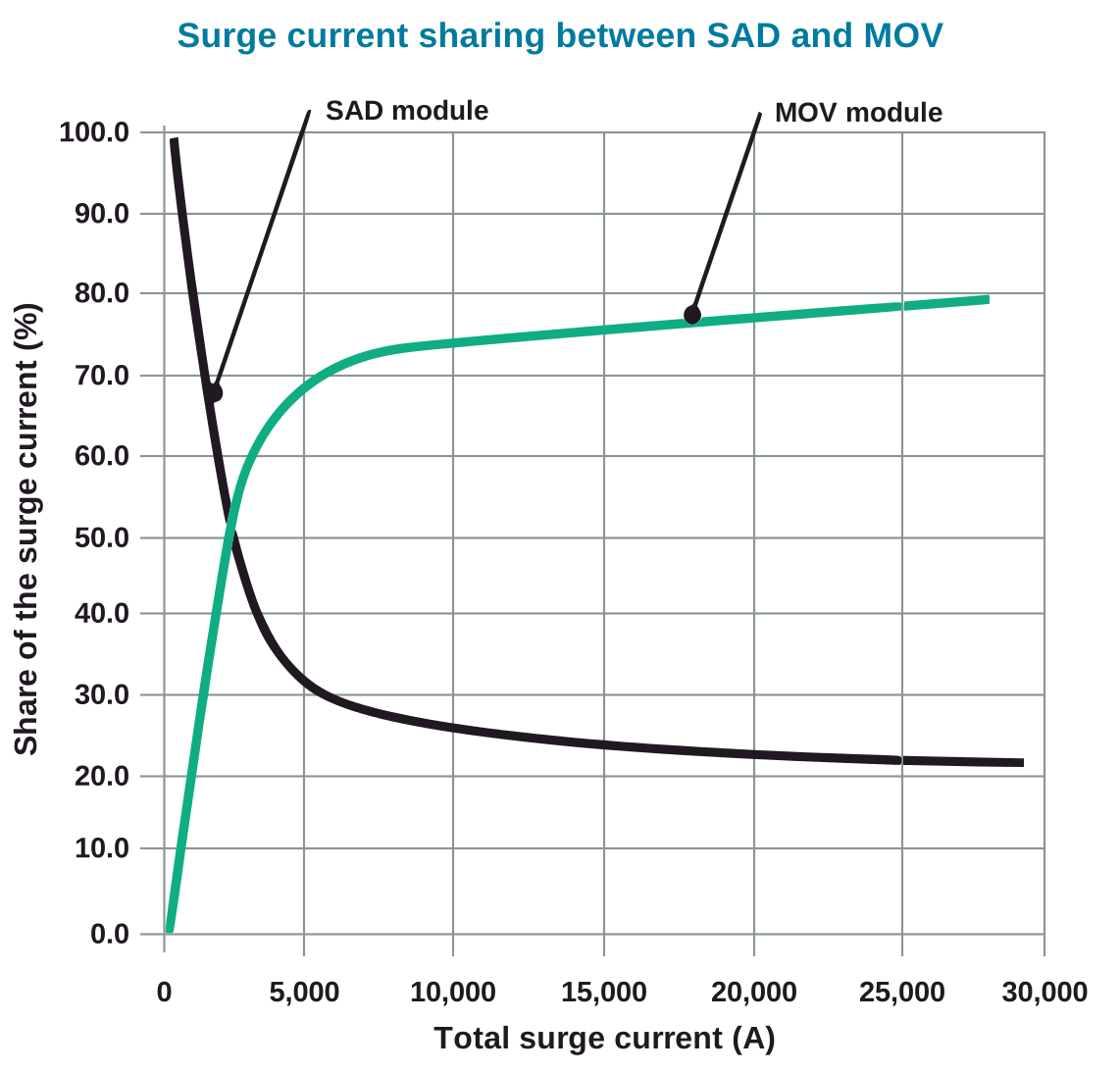
In fast-response hybrid designs, an MOV may be combined with silicon avalanche diode (SAD) elements. This combination uses the fast response of the semiconductor element together with the energy-handling capability of the varistor section.
6. Testing: 10/350 μs, 8/20 μs and the combination wave
Real lightning and switching surges are never perfectly identical. Standards therefore use defined waveforms to compare devices and verify their withstand performance.
- 10/350 μs — a waveform associated with high-energy surges and Type 1 / Class I testing.
- 8/20 μs — a surge current waveform for Type 2 / Class II testing.
- Combination wave — used for Type 3 / Class III testing and verification of sensitive electronic equipment protection.
- TOV — verification of device behaviour under temporary overvoltages that last substantially longer than a surge.
7. Degradation and status monitoring
Varistor SPDs age progressively. After repeated surges or a single severe event, a protective element may partially lose its ability to limit overvoltage. For critical facilities, the rated kA value therefore needs to be considered alongside operational status indication, thermal protection and remote signalling.
For industrial standby power systems, useful features include volt-free alarm contacts, visual status indication, surge counters and the ability to transmit a signal to the ATS, BMS or SCADA system.
8. What this means for STAVR ATS equipment
For ATS equipment, LV switchboards, UPS, BESS and control systems, an SPD should be treated as part of the power supply system rather than an additional module. The ATS transfers sources, but during lightning events, switching or internal surges, electronics, controllers, power supplies, communication interfaces and control coils are the first components exposed to hazardous overvoltages.
Applications and selection data are described on the SPDs in ATS equipment and LV switchboards page.
9. Practical application considerations
SPD effectiveness depends on more than the device data sheet. Installation location, connection length to the busbars, the quality of the PE conductor, the earthing system, equipotential bonding and coordination between protection stages all have a significant effect.
For surges with a nanosecond-range front, connection geometry matters as well as conductor length: routing, avoidance of loops and unnecessary bends, and conductor spacing. A short connection must be arranged to avoid introducing additional inductance into the surge current path.
Even a high-quality SPD may be ineffective if it is installed far from the incoming supply point, connected with long conductors or poorly routed. The design should therefore treat the SPD as part of the facility power supply system rather than an isolated module.
10. Conclusion
The European Type 1 / Type 2 / Type 3 cascade and the US UL / IEEE approach should not be treated as opposing concepts. For a critical facility, they complement each other: robust protection is required at the incoming supply, coordinated protection in distribution switchboards, and control of residual surges near sensitive electronics.
The right SPD is more than a high current figure in a data sheet. It combines verified construction, correct installation location, short connections, proper earthing, status indication and a clear maintenance procedure.
Sources and standards
This material is a technical overview of SPD selection and application principles in standby power systems. It uses and adapts earlier ESL / STAVR technical material on SPDs, multi-stage protection systems, hybrid MOV/SAD solutions, 10/350 μs and 8/20 μs testing, UL 1449 and IEEE C62.41 / C62.45.
The following technical publication was also considered: Kniaziev V., “Technical requirements for surge protective devices for the power supply ports of technical equipment”, “Standardisation, Certification, Quality”, No. 2(75), 2012, pp. 46–51.
- Bibliographic record at the Vernadsky National Library of Ukraine
- 2012 publications of the Molniya Research and Design Institute, NTU KhPI
The approaches in IEC 61643-11, DSTU IEC 61000-4-5, UL 1449 and IEEE C62.41 / C62.45 concerning the testing, classification and application of surge protective devices were also considered.