
SPD in ATS, LV switchboards, UPS, BESS and control systems
In STAVR equipment, the SPD is part of a complete standby power solution designed for the facility’s power arrangement, earthing and surge exposure. The solution aims to prevent damage to controllers, power supplies, UPS, BESS, control systems and power equipment from brief lightning, switching and internally generated surges.
Why one small module is not enough
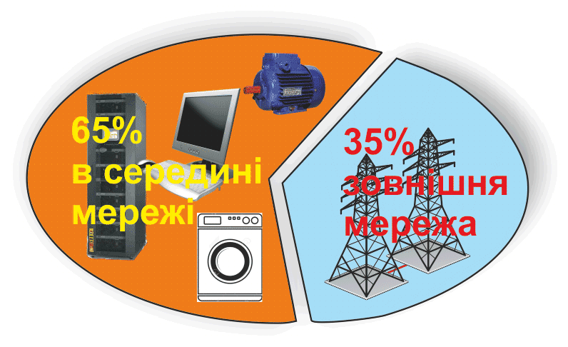
Transient overvoltages can originate outside the building, from lightning, induced effects or switching in the power system. However, a substantial proportion of disturbances originates inside: motors, contactors, variable frequency drives, UPS, switched-mode power supplies and control systems.
- external surges are less frequent but carry more energy and can cause equipment failure;
- internal surges are more frequent and can cause controller malfunctions;
- protection must cover the whole system: incoming supply, distribution and sensitive equipment.
Where we install SPD
SPD is an integral part of power supply reliability, not simply an accessory fitted in a panel.
ATS and LV switchboards
Protection of incoming supplies, busbars, transfer controls, controllers, interlocks and control circuits.
Generator and utility supply
Reducing the risk of damage during lightning, fault and switching events.
UPS and BESS
Protection of sensitive electronics, bypass circuits, charging modules and power modules.
Automation
Protection of PLCs, controllers, BMS/SCADA, communications modules, sensors and power supplies.
Why an ATS needs SPD
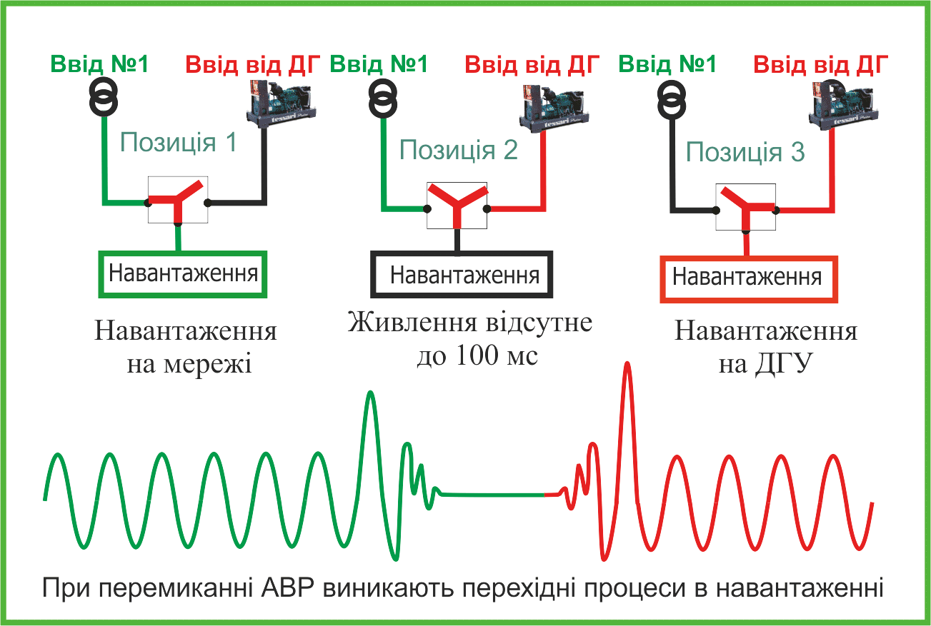
An ATS interfaces between two power sources: the normal utility supply and the generator. Transferring the load from one source to the other can produce brief voltage dips, surges and transient overvoltages.
- the ATS is connected to the utility supply, generator and load;
- the controller, power supplies, coils, interfaces and signalling circuits are sensitive to short surges;
- SPD within an ATS reduces the risk of equipment damage and intermittent faults after transfers, thunderstorms or supply faults.
SPD status indication and monitoring
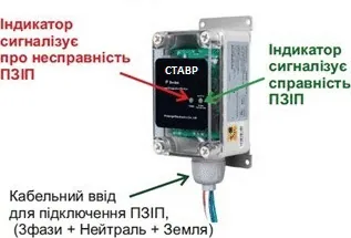
At critical facilities, an SPD must be monitored as well as installed. After a severe surge or gradual degradation of the protective element, the system should indicate that the module needs inspection or replacement.
- local healthy/fault indication;
- a volt-free contact for signalling to the ATS, BMS or SCADA;
- separate phase, neutral and protective conductor connections;
- clear status information for maintenance personnel.
Coordinated protection stages
For a critical facility, SPD is selected according to the installation location, surge energy and permissible residual voltage, rather than its designation alone.
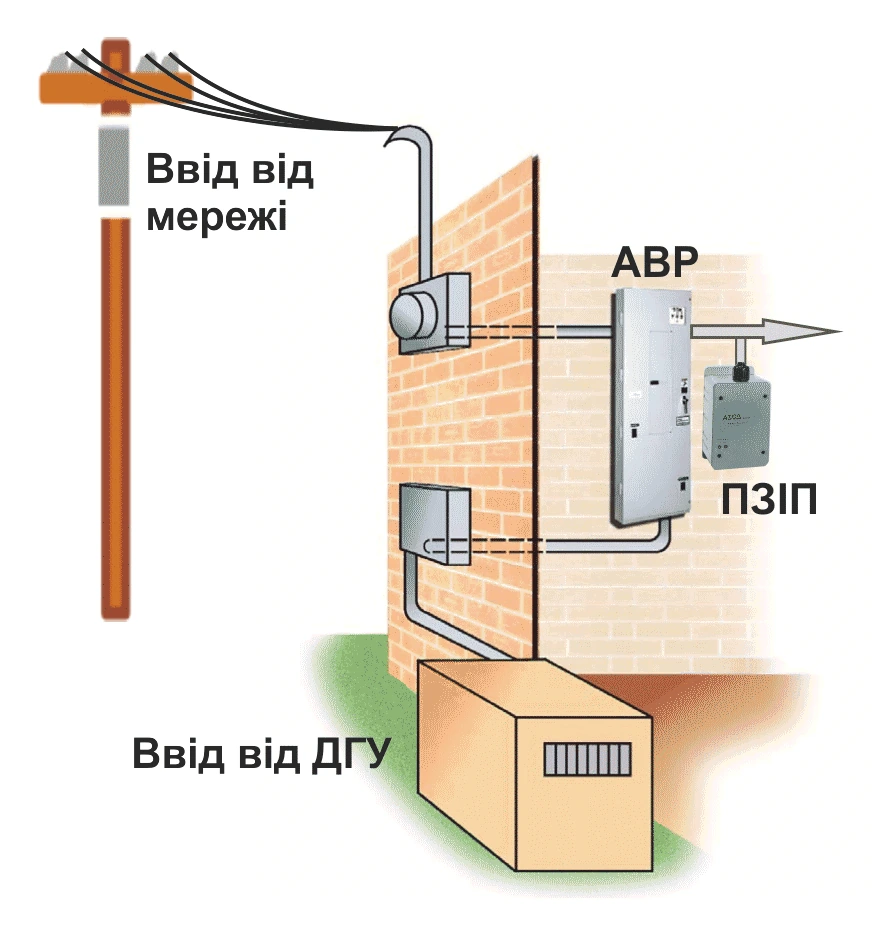
Building service entrance
The high-capacity protection stage absorbs the main energy of an external surge before it propagates further into the system.
Distribution boards
The second stage reduces residual overvoltage and protects supply sections, ATS, LV switchboards and cable circuits.
Sensitive equipment
The final stage protects controllers, communications, automation, UPS, BESS and electronic modules.
High-capacity protection at the incoming supply plus coordinated stages inside the building
The European Type 1 / Type 2 / Type 3 approach and the American UL / IEEE approach do not conflict. They complement each other: external surges must be handled at the incoming supply, while internal and residual disturbances must be attenuated closer to the equipment.
STAVR solutions use industrial-grade SPD certified to UL 1449. This certification applies specifically to the SPD component installed in the cabinet. The overall solution is designed for the facility, power supply arrangement, earthing system and surge exposure.
What we check during selection
Benefits for the customer
- lower risk of failure of controllers, PLCs, power supplies and communications modules;
- fewer intermittent control faults after thunderstorms and switching events;
- SPD status monitoring through indication or a volt-free contact;
- protection of both the power section and the standby power system’s control logic;
- provision for SPD in a complete ATS or LV switchboard specification.
Send the specification or power supply diagram
For preliminary selection, provide the voltage, supply system type, number of incoming supplies, power sources, installation location, earthing arrangement and SPD status signalling requirements.
Expand the technical explanation for engineers
How an SPD works
An SPD has a high impedance in normal operation. When a short overvoltage surge occurs, the protective element rapidly reduces its impedance and diverts surge current to the protective conductor or between conductors, limiting the voltage to a safer level.
Protection modes
Different systems may use L-L, L-N, L-G and N-G combinations. The supply and earthing arrangements determine which surge paths require protection.
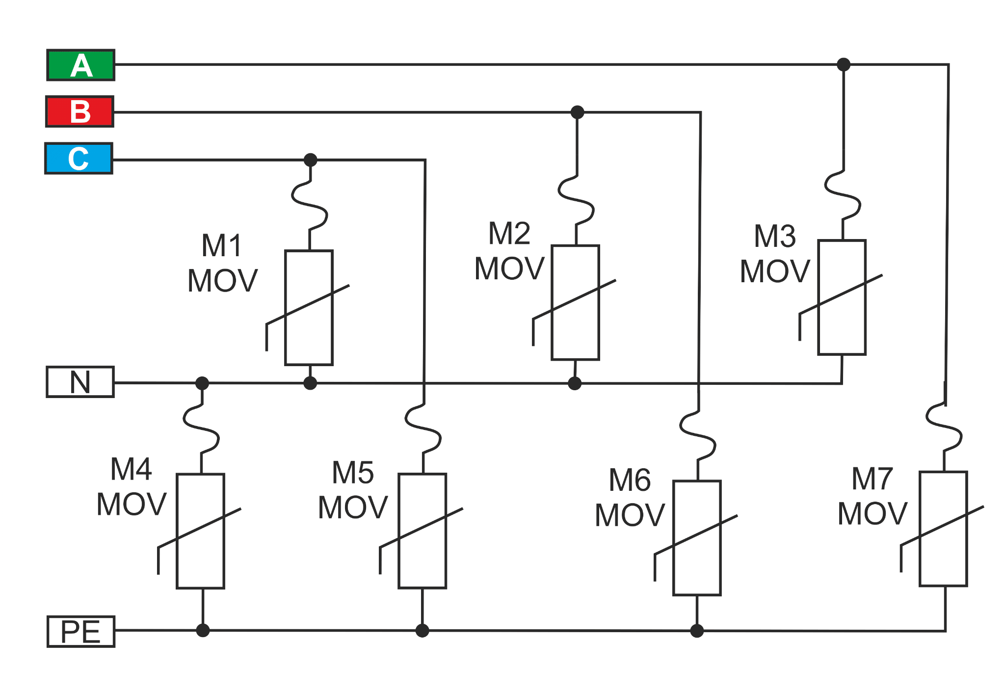
Why SPD is not selected by the ATS operating current
An SPD is not a series-connected power device and does not carry the load operating current. The key selection criteria are its ability to withstand surge current and provide the required residual voltage level.
Status monitoring
Varistor elements have a finite service life and degrade after repeated surges. For critical facilities, provision should be made for status indication, an alarm contact and signalling to BMS or SCADA.
Sources and standards. This material draws on IEC 61643-11, DSTU IEC 61000-4-5, UL 1449, IEEE C62.41 / C62.45 and V. Kniaziev’s technical paper “Technical Requirements for Surge Protective Devices for Equipment Power Supply Ports”, Standardisation, Certification, Quality, No. 2(75), 2012, pp. 46–51.