
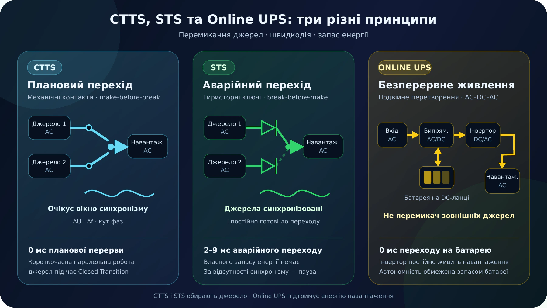
CTTS and STS have two inputs and can transfer the load only to a second source that is available and within acceptable limits. For closed transition, both sources must be available and acceptable at the same time. The CTTS monitors voltage, frequency and phase-angle differences, waits for the sources to enter the specified synchronism window and then performs a planned transfer with 0 ms interruption of supply. Continuous source synchronism is not required. By contrast, to guarantee an emergency STS transfer in 2–9 ms, its two sources must remain continuously synchronised: the active-source failure cannot be predicted, so the STS cannot wait for synchronism after the fault. If synchronism is absent, fast transfer is inhibited or performed with a delay; in terms of the effect on the load, the STS loses its advantage over a conventional ATS. An online UPS does not replace the ATS: it temporarily powers the load from a battery with a finite energy reserve. In a generator-backed system, the UPS supports the load while the generator starts, and the ATS connects it to the UPS input.
Unsure which architecture you need? Describe the sources, load and permissible interruption: a STAVR engineer will help determine whether you need CTTS, STS or an ATS combined with an online UPS.
Request technical selection1. Why these systems are confused
CTTS and STS perform a switching function: they monitor two AC sources and connect the load to one of them. Neither device has its own stored energy. If the second source is absent or unacceptable, there is nowhere to transfer the load.
An online UPS performs an energy-supply function: its inverter supports the load from the DC link and battery when the incoming utility supply fails. However, this mode is limited by the available autonomy. Once the battery is discharged, power will also be lost unless another AC source is connected to the UPS input.
2. CTTS and STS operating principles and the role of an online UPS
Mechanical contacts
A Closed Transition Transfer Switch connects the new source before disconnecting the previous one. The sources briefly operate in parallel, so the control system checks voltage, frequency, phase sequence and the phase angle between the sources before transfer. The CTTS does not synchronise the sources; it waits until they enter the specified synchronism window naturally. For example, with ASCO Closed Transition, the magnitude of the phase-angle difference must be less than 5° (within ±5°), the frequency difference less than 0.2 Hz and the voltage difference less than 5%; for other models, the limits are specified by the manufacturer.
Semiconductor switches
A Static Transfer Switch uses power thyristors or other semiconductor switches. It disconnects the unacceptable input and connects an acceptable second input using the break-before-make principle. Because a fault can occur at any moment, guaranteed transfer in 2–9 ms requires the STS sources to remain continuously synchronised and the controller to continuously confirm acceptable voltage, frequency and phase-angle differences. If synchronism is lost, fast switching is inhibited and a delay is introduced before the load can be safely reconnected.
Double conversion
The incoming AC voltage is converted to DC, and the inverter converts it back to AC for the load. The battery is connected to the DC link. In a typical integrated arrangement, the UPS receives the source already selected by the ATS, whether utility or generator, and does not perform the function of an external ATS.
3. What happens when the active source suddenly fails
CTTS
If the active source has already failed, the second source cannot be connected before the first source is lost: the first source is effectively no longer available. The CTTS waits for the standby source to become available and ready, then performs a conventional transfer with an interruption. In a utility–generator arrangement, generator starting and stabilisation time adds to this interruption.
STS
The STS detects that the active input is unacceptable, stops conduction from it and connects an acceptable alternative input. If no acceptable second source exists, the STS cannot support the load. If the standby source was synchronised with the active source at the moment of the fault, transfer takes approximately 2–9 ms with a minimal phase jump.
In practice, industrial loads are mixed. In addition to motors and transformers, they include switch-mode power supplies, rectifiers, variable-frequency drives and inverters with charged DC buses. An abrupt phase change can cause an input-capacitor recharge pulse, a current surge, loss of synchronisation in an electronic converter, protective-device operation or an overload of the STS power thyristors.
Online UPS
In double-conversion mode, the inverter continues to power the load from the DC link, while the battery compensates for the loss of incoming energy. Transfer to battery therefore takes zero time. However, autonomy is limited: if the utility supply does not return and the ATS does not supply generator power to the UPS input before the battery is discharged, the output voltage will be lost.
4. Comparison table
| Criterion | CTTS | STS | Online UPS |
|---|---|---|---|
| Primary function | Controlled transfer between two sources, including uninterrupted supply during a permitted transfer | Fast selection of one of two independent AC sources | Continuous, regulated power to the load |
| External sources | Two monitored inputs | Two monitored inputs | In a typical arrangement, one input already selected by the ATS; the battery is a temporary internal energy source. A separate bypass input does not make the UPS a substitute for an external ATS |
| Power switching element | Electromechanical contacts | Semiconductor switches, predominantly thyristors | Rectifier, DC link, inverter, battery and static bypass |
| Parallel source operation | Yes, momentarily during closed transition | No; typical operation is break-before-make | Not the principle used to supply the load; the sources are separated by power converters |
| Phase-alignment monitoring | Continuous synchronism is not required. For closed transition, the controller must detect that two available, acceptable sources have entered the specified voltage, frequency and phase-angle difference window | To guarantee an emergency transfer in 2–9 ms, both sources must remain continuously synchronised and the STS must continuously monitor voltage, frequency and phase-angle differences | Not a condition for transfer to battery: the inverter continuously supplies the load |
| Planned transfer | 0 ms interruption of supply when both sources are available, acceptable and within the specified synchronism window | Between synchronised sources, typically 2–9 ms. Without synchronism, a design-specified delay is required, approximately 3–5 s | Does not transfer the load between two external sources; this is the function of the ATS upstream of the UPS |
| Transfer following sudden input failure | With an interruption; for a generator set, after starting and stabilisation | Approximately 2–9 ms if the standby source is acceptable and synchronised with the active source at the moment of failure. Without synchronism, a delay is required until safe load reconnection is possible | 0 ms to battery in double-conversion mode |
| Stored energy | None | None | Yes, in a battery or another DC energy-storage device |
| Voltage-quality correction | No; the load receives the electrical characteristics of the selected source | No; the load receives the electrical characteristics of the selected source | Yes; the inverter generates the output voltage within the UPS specifications |
| Typical loads | Industrial, commercial and infrastructure loads. For a planned, uninterrupted transfer between two generator sets, the CTTS monitors voltage, frequency and phase angle, waits for both sources to enter the specified synchronism window and then performs closed transition | Single-input critical loads with two independent, conditioned sources available | Servers, control systems, communications, medical equipment and other loads that cannot tolerate an interruption |
| Main limitation | Uninterrupted transfer is possible when both sources are available and acceptable simultaneously and the CTTS detects that they have entered the specified synchronism window. Continuous source synchronism is not required | Two continuously synchronised, acceptable sources are required. Without synchronism, fast transfer in 2–9 ms is lost; a delay and checks of inrush and STS surge capability are required, and the effect on the load is that of an ATS with an interruption | Once battery energy is exhausted, power is lost unless the ATS connects the utility supply or generator; batteries require maintenance |
5. Typical appropriate combinations
Source transfer and maintenance arrangements around the UPS are covered on the ATS solutions for UPS systems page.
6. How to select a system
When CTTS is needed
Two high-power AC sources are available; planned transfers between sources are required without stopping the load; an interruption during a source failure is acceptable, or the critical part of the load is protected by a separate UPS.
When STS is needed
Two independent, continuously ready and synchronised sources are available; the load has a single input; emergency transfer in 2–9 ms is required. If continuous source synchronism cannot be maintained, the main advantage of the STS is lost.
When an online UPS is needed
Even a short interruption causes a shutdown, data loss or disruption to a process. The battery must provide enough autonomy to wait for the generator set to become ready or to complete a safe shutdown.
When a combination is needed
For a critical load that cannot tolerate an interruption and uses a generator set as the standby source. The ATS manages the utility and generator supplies, the UPS bridges the generator starting time and, after transfer, continues powering the load from the generator.
7. Five common technical misconceptions
- “CTTS always transfers without an interruption.” No. A planned closed-transition transfer requires two sources that are simultaneously available and acceptable. The CTTS waits for them to enter the specified synchronism window and performs uninterrupted transfer at that moment. If the active source has already failed, transfer will include an interruption; if both sources are present but the window has not been reached, closed transition is delayed or inhibited according to the controller settings.
- “STS is a type of UPS.” No. An STS is a solid-state transfer switch. It has no energy storage and cannot continue supplying the load if both power sources are absent.
- “Electronic loads can always withstand a phase jump.” No. Switch-mode power supplies, rectifiers, inverters and variable-frequency drives can produce a high transient current and overload the STS. Guaranteed fast transfer therefore requires the STS sources to remain continuously synchronised.
- “An online UPS takes a few milliseconds to switch to battery.” In normal double-conversion operation, the load is continuously supplied by the inverter, so transfer to battery takes 0 ms.
- “A UPS can supply the load indefinitely after utility power fails.” No. A UPS only uses the battery's calculated energy reserve. Sustained operation requires restoration of the utility supply or connection of a generator set through the ATS.
8. Conclusion
The main difference between STS and CTTS is how and when transfer takes place. An STS must perform an emergency transfer at an unpredictable moment, so its two sources must remain continuously synchronised to guarantee transfer in 2–9 ms. Without synchronism, fast transfer is inhibited or performed with a delay; in terms of its effect on the load, the STS operates like a conventional ATS with an interruption.
A CTTS does not synchronise the sources or require them to remain continuously synchronised. For a planned closed-transition transfer, two sources must be simultaneously available and acceptable. The controller waits until the voltage, frequency and phase-angle differences enter the specified synchronism window, then briefly parallels the sources and transfers without interrupting the supply (0 ms). If one source has already failed, the CTTS transfers with an interruption. If both sources are present but the synchronism window has not been reached, closed transition is delayed or inhibited according to the controller settings.
An online UPS is not a transfer switch and should not be classified as a source-transfer device. It provides uninterrupted power using a finite energy reserve stored in its battery. In a system with an ATS and generator set, it supports the critical load while the generator starts, after which the ATS connects generator power to the UPS input.
Official technical sources
- Schneider Electric / ASCO: automatic transfer switch transition modes
- Schneider Electric / ASCO: synchronism conditions for closed transition
- Vertiv: industrial STS operating principle and transfer speed
- Eaton: fast in-phase and special VSS transfer algorithms for STS
- Eaton: double-conversion online UPS
We will select an arrangement for your facility
Send details of the power sources, load power or current and the permissible interruption duration. We will identify the appropriate architecture — CTTS, STS, an ATS with an online UPS or a combination — and prepare an engineering solution.