No-break
ATS
Solutions for facilities where even a brief interruption during transfer between sources can cause a UPS to switch to battery power, trigger a controller fault, stop an automation system or cause an unwanted restart of process equipment.
ATS with no interruption to the supply
A no-break ATS monitors the availability and quality of the normal mains supply, receives the standby source availability signal and transfers the load so that it does not lose power at the critical moment.
This solution is used where even a brief interruption during transfer could cause a UPS to switch to battery power, trigger a controller fault, stop an automation system or cause an unwanted restart of process equipment.
In STAVR products, the transfer switch, controller, protection, interlocks, indication and connection terminals work as a single system. A no-break ATS is therefore more than a faster switch: it is a complete backup power control panel for critical loads.
The ATS configuration is selected to suit the current, voltage, number of poles, load type, generator operating mode, and requirements for manual operation, interlocking, indication, supervisory monitoring and service access.
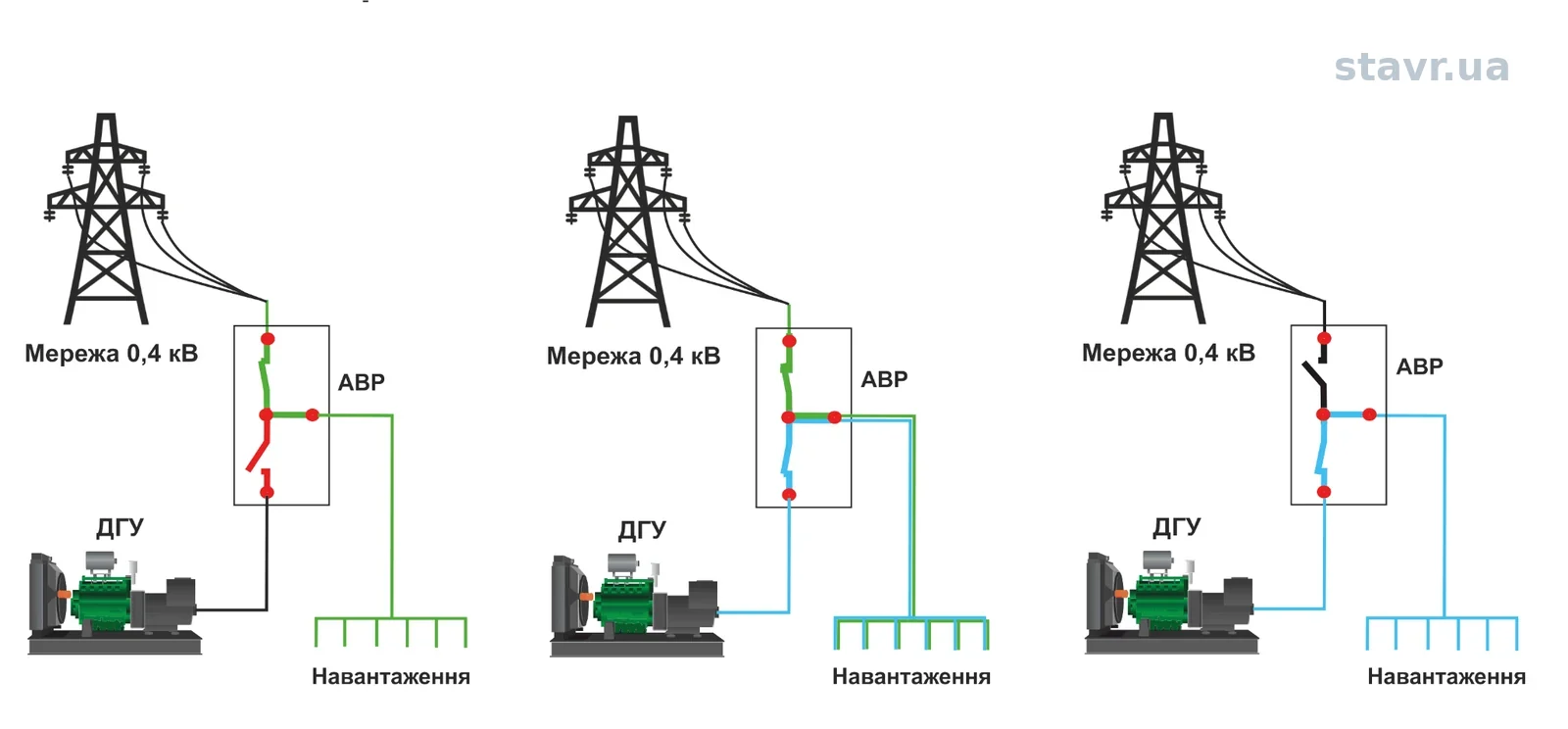
CTTS sequence diagram: the load transfers from the 0.4 kV mains supply to the diesel generator through a controlled, momentary contact-overlap stage.
During this transfer, the system monitors voltage, frequency, phase angle and the permissible duration of parallel source operation so that the critical load does not lose power. The diagram illustrates the transfer logic, not a specific power-section design.
No-break ATS features
Basic parameters for preliminary selection
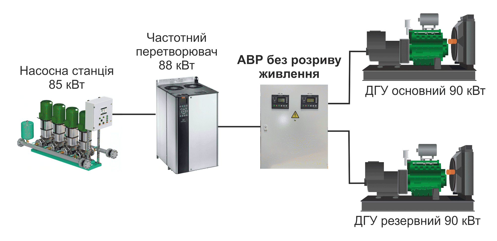
Pumping station with two diesel generators and no interruption to the supply
An example arrangement in which a no-break ATS supplies a pumping station through a variable frequency drive and allows transfer between the duty and standby diesel generators without an unwanted interruption to the process.
Send information for ATS selection
For preliminary selection, a brief description of the power sources, load, current, voltage and operating conditions is sufficient. A photograph of the existing panel or main distribution switchboard will help us assess the solution more quickly, but is not essential.