ATS for UPS
Solutions for automatic or service transfer of critical loads between UPS, a bypass line, utility supply, generator or another standby source. An ATS complements the UPS by integrating it correctly into the facility’s standby power system.
A UPS protects the load but also needs the right switching arrangement
A UPS handles voltage dips, short interruptions and some power quality problems. However, proper power switching is required when the UPS needs servicing, replacement, transfer to bypass or backup by a second UPS. This is where the ATS becomes part of the power continuity system.
A controlled power path as well as a UPS
The order of components can vary by project. What matters is coordinated operation: which source supplies the load normally, what happens if the UPS fails, how servicing is performed and how the system returns to normal operation.
Applications for ATS with UPS
An enquiry for “ATS for UPS” can refer to different requirements. Select a scenario to open a panel below with a diagram and a brief explanation.
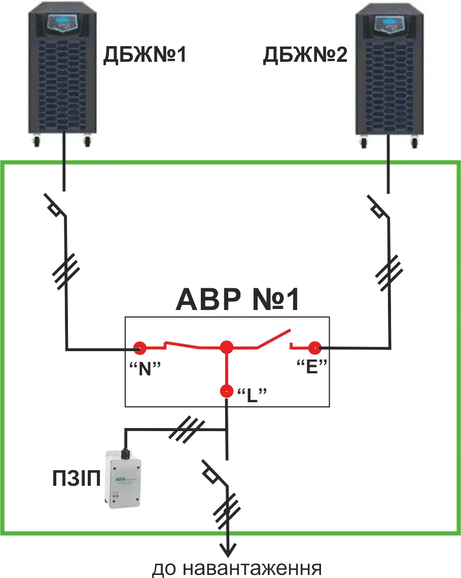
Two UPS units → one critical load
The ATS monitors the outputs of two independent UPS units and transfers the load to the standby UPS if the primary UPS has a fault, is overloaded, switched off or taken out of service.
This configuration provides redundancy for the uninterruptible power system itself, as well as for the utility or generator supply.
- server rooms, telecommunications facilities and control systems;
- facilities where one UPS must not be a single point of failure;
- servicing or replacement of one UPS without interrupting the critical load.
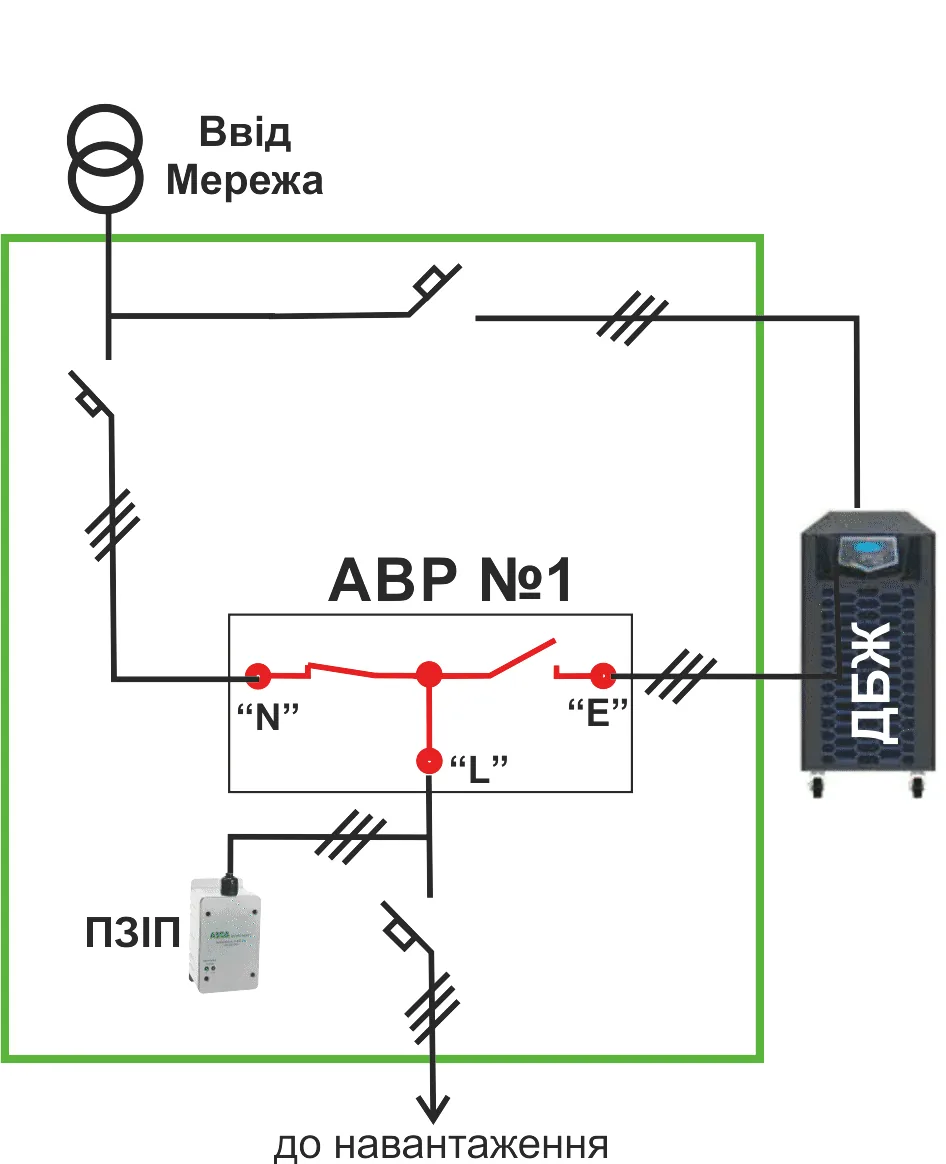
UPS / bypass line
A bypass is needed for UPS servicing, testing or replacement. The load can be transferred to the bypass line using an agreed procedure and the necessary interlocks.
This provides system maintainability rather than replacing the UPS: the facility should not depend on a single device without a clear manual operating procedure.
- UPS servicing or replacement;
- emergency operation when the UPS is temporarily unavailable;
- load transfer using an orderly manual procedure.
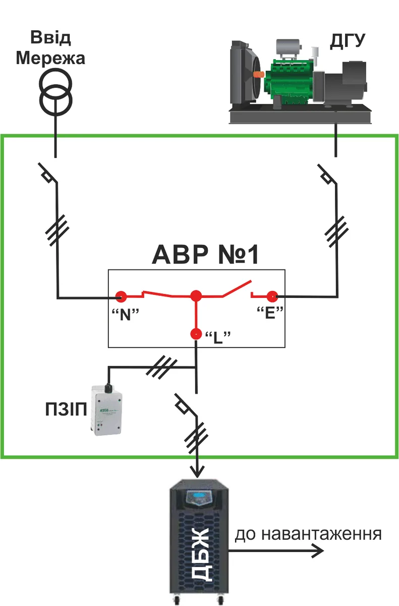
Utility / generator upstream of the UPS input
In this configuration, the ATS is installed upstream of the UPS and connects its input to the normal utility supply or the standby generator. The critical load remains protected by the UPS.
The generator, voltage quality, transfer delays and permissible UPS operating modes must be coordinated to avoid unnecessary UPS battery operation.
- generator backup for the UPS input;
- facilities requiring extended autonomous operation from a generator;
- systems where the UPS must bridge brief voltage dips during transfer.
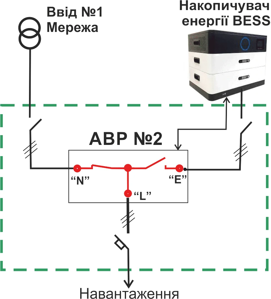
UPS / BESS / inverter
In modern standby power systems, a UPS can operate alongside BESS, an inverter, a generator or the utility supply. In this arrangement, the ATS provides controlled load transfer between sources.
It is essential to prevent backfeed, disconnect the load from the utility supply correctly and provide a clear sequence for transfer to the battery system.
- facilities with battery backup or BESS;
- systems with an inverter, UPS and generator;
- controlled load transfer between the utility supply and energy storage.
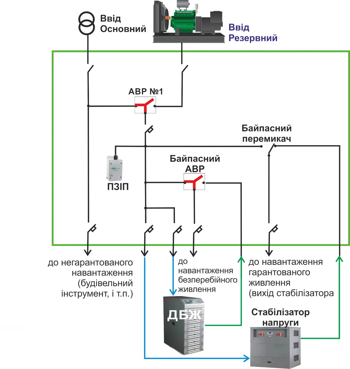
Integrated system with UPS, voltage stabiliser, SPD and bypass
In practice, a UPS often operates together with an ATS, voltage stabiliser, SPD and bypass line. Loads can be divided into groups: non-backed-up loads, uninterruptible loads and backed-up loads downstream of the voltage stabiliser.
This arrangement shows that an ATS alongside a UPS is part of the overall standby power and service access strategy.
- separation of loads by priority;
- SPD protection for control and power circuits;
- bypass for servicing and emergency manual operation.
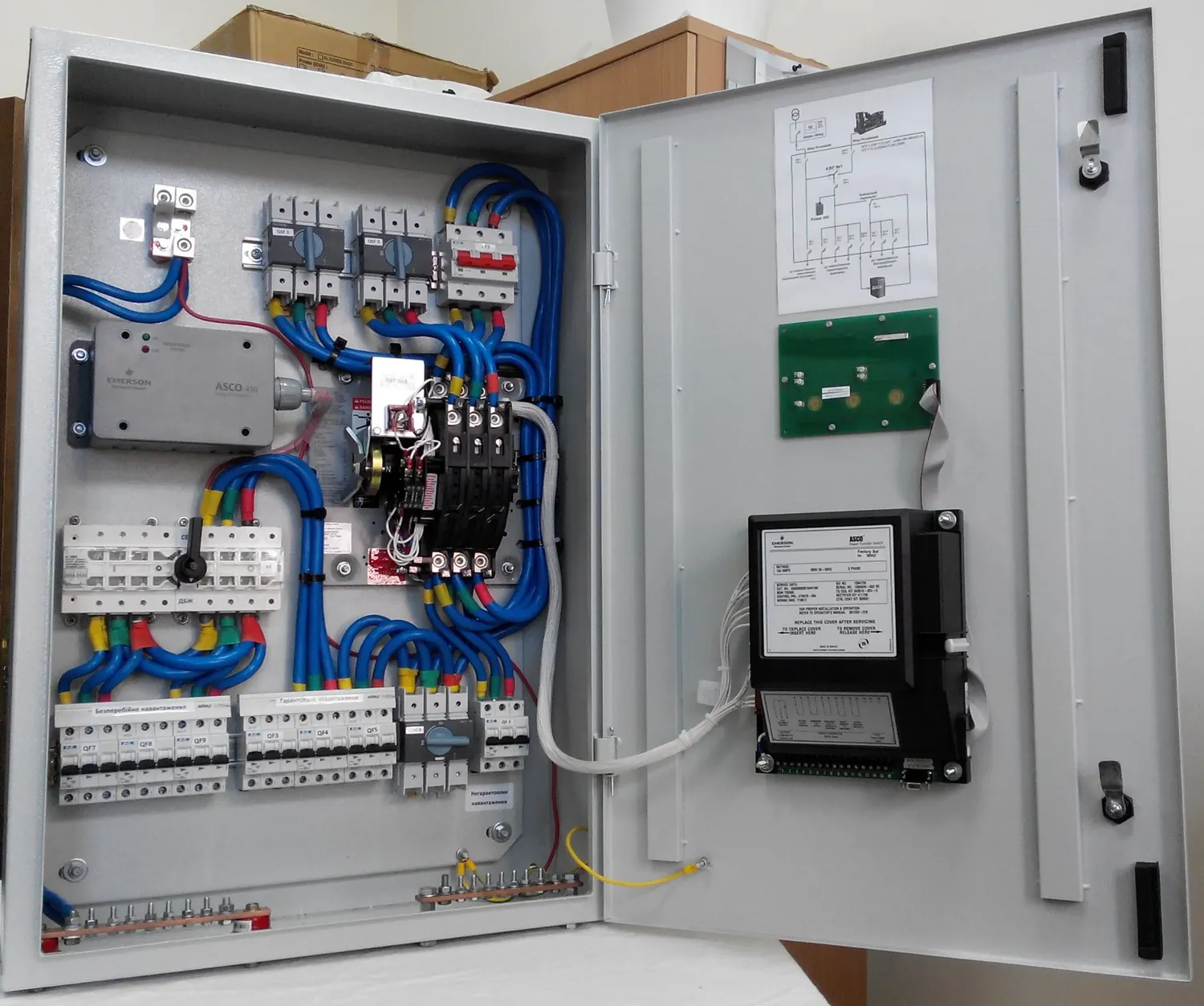
UPS operation depends on more than voltage availability
In UPS systems, a switching error can be as serious as a utility failure. The ATS must therefore account for source quality, UPS status, bypass mode, manual operation and alarm signals.
Source status
Monitoring voltage availability and quality at incoming supplies, UPS outputs or bypass lines.
Service mode
Provision for safely taking the UPS out of service using a manual or automated transfer sequence.
Interlocking
Protection against incorrect operating states, backfeed and operator errors.
Monitoring
Transmission of status, alarms, switch position and the event log to a supervisory or smart control system.
Manual bypass
A clear emergency and maintenance procedure when the automatic controls or UPS are temporarily unavailable.
Critical load
Servers, network equipment, automation, controllers, medical or process systems.
What information to provide
For preliminary selection, describe the power supply arrangement: number of UPS units, bypass, generator or BESS, voltage / phases, load current, UPS / BESS rating and the required operating mode.
Attach panel photographs, a single-line diagram or a specification to the enquiry form if available. This helps determine the appropriate transfer logic, service mode and interlocks more quickly.
ATS for UPS supports continuity across the whole system
Even a high-quality UPS cannot meet every standby power requirement without a suitable switching arrangement, bypass, interlocks, indication and service access. STAVR ATS helps make a UPS system clear to operate, safe for equipment and maintainable.
For preliminary selection, describe the power supply arrangement, number of UPS units, generator or BESS, load current, bypass and service mode requirements.
Send information for ATS selection for UPS
Describe the power supply arrangement, number of UPS units, bypass, generator or BESS, load current and required operating mode. A panel photograph or single-line diagram will help us assess the solution more quickly.