
1. What is an ATS?
How to select an ATS by rated current and load — an explanation of Ith, Ie and utilisation categories using examples from rated characteristics.
An ATS—automatic transfer switch—is a complete low-voltage transfer switching assembly designed to monitor power sources and automatically connect the load to an available, serviceable source.
In practice, an ATS is more than a cabinet with controls: it is part of the power distribution system. It includes the power transfer switching device, control system, interlocking, indication, monitoring circuits and additional protective devices.
The main purpose of an ATS is to transfer the load safely between power sources, preventing unintended interconnection of the sources and connection to a source that is not ready or whose quality is unacceptable.
2. Standards and terminology
Correct ATS selection requires a distinction between the everyday term ATS cabinet and the standardised concept of transfer switching equipment. IEC / EN 60947-6-1 uses the term transfer switching equipment.
For modern projects, the following standards and requirements provide an appropriate basis:
- DSTU EN 60947-6-1:2018 — low-voltage switchgear and controlgear, multiple function equipment, transfer switching equipment;
- IEC / EN 60947-6-1 — the fundamental international and European framework for this equipment;
- UL 1008 — the standard for transfer switch equipment, often used for industrial and critical facilities;
- project and technical specification requirements, power supply reliability category and load characteristics.
3. Classification of transfer switching equipment
Transfer switching equipment may be manually operated, remotely operated or automatic. In the usual engineering sense of an ATS, the key type is automatic transfer switching equipment, which independently monitors the sources and transfers according to defined logic.
| Equipment type | Meaning | Applications |
|---|---|---|
| Manually operated transfer switching equipment | An operator performs the transfer manually. | Simple systems, maintenance arrangements and standby manual operating modes. |
| Remotely operated transfer switching equipment | The transfer command is issued remotely. | Systems with duty personnel or supervisory control. |
| Automatic transfer switching equipment | Transfer takes place automatically according to defined logic. | ATS for generators, UPS, BESS and critical building services systems. |
4. Classes PC, CB and CC
Standards also classify transfer switching equipment according to its ability to make, withstand or break short-circuit currents. This parameter is critical for safety and correct coordination with protective devices.
| Class | Meaning | Engineering comment |
|---|---|---|
| PC | Equipment capable of making and withstanding short-circuit current, but not intended to break it. | Correct coordination with upstream fuses or circuit breakers is required. |
| CB | Equipment with overcurrent releases that can break short-circuit currents. | Combines transfer with protection, but the construction is often more complex and transfer is slower. |
| CC | Equipment based on devices complying with IEC 60947-4-1, capable of making and withstanding short-circuit current. | Requires particularly careful verification of compliance and application conditions. |
5. Utilisation categories
The utilisation category defines the type of load with which a transfer switching device can operate. For ATS equipment in industrial and critical facilities, AC-33B is particularly important because it covers mixed loads, including motors.
| Category | Load type | Practical meaning |
|---|---|---|
| AC-31 | Resistive or slightly inductive load. | Simple loads without significant starting currents. |
| AC-32 | Mixed resistive and inductive loads. | General industrial loads with moderate starting transients. |
| AC-33B | Motors or mixed loads including motors, resistive loads and some lighting. | An appropriate reference category for ATS equipment in critical systems with fans, pumps, compressors, IT loads and building services infrastructure. |
Contactor endurance is not the same as ATS endurance
Many ATS descriptions quote contactor endurance in thousands of cycles. This parameter alone, however, does not determine the reliability of an automatic transfer system.
For an ATS, the number of operations is only part of the picture. The conditions of those operations also matter: load characteristics, starting currents, voltage dips, short-circuit withstand capability, mechanical interlocking, power contact position monitoring and prevention of unintended interconnection between sources.
A contactor may have a high declared endurance, but this does not automatically mean that the complete ATS meets the requirements for power transfer switching equipment. A professional ATS must be assessed as a complete switching product under IEC / EN 60947-6-1, taking account of its utilisation category, including AC-33B.
The right selection question is therefore not “How many cycles is the contactor rated for?”, but “Does the complete ATS comply with category AC-33B, at what rated current is this verified, and how does the assembly withstand fault conditions?”
ATS transfer time
Fast transfer can be an important advantage, particularly for equipment sensitive to prolonged supply interruptions: electric motors, UPS units, servers, controls, power supplies and process systems.
However, transfer time must be considered alongside ATS construction and operating logic. A high-quality ATS transfers the load not merely quickly, but in a controlled manner that is safe for the particular power supply system.
Some facilities require the shortest possible supply interruption. Others require an appropriate time delay, generator starting, voltage and frequency stabilisation or coordinated operation with a UPS. The optimum transfer time is therefore determined by the facility purpose and load characteristics, rather than an advertising figure.
Important: ATS transfer speed matters, but it must be combined with correct operating logic and suitable switching assembly construction. ATS selection should therefore assess not only operating time, but also whether the solution suits the specific load and power sources.
An ATS is therefore selected not only by rated current and transfer speed, but with regard to the complete system: power sources, load type, operating duty and continuity of supply requirements.
6. Main ATS construction types
In practice, an ATS may be built around different types of switching devices. The construction affects transfer speed, endurance, fault withstand capability, manual operating provisions and safety.
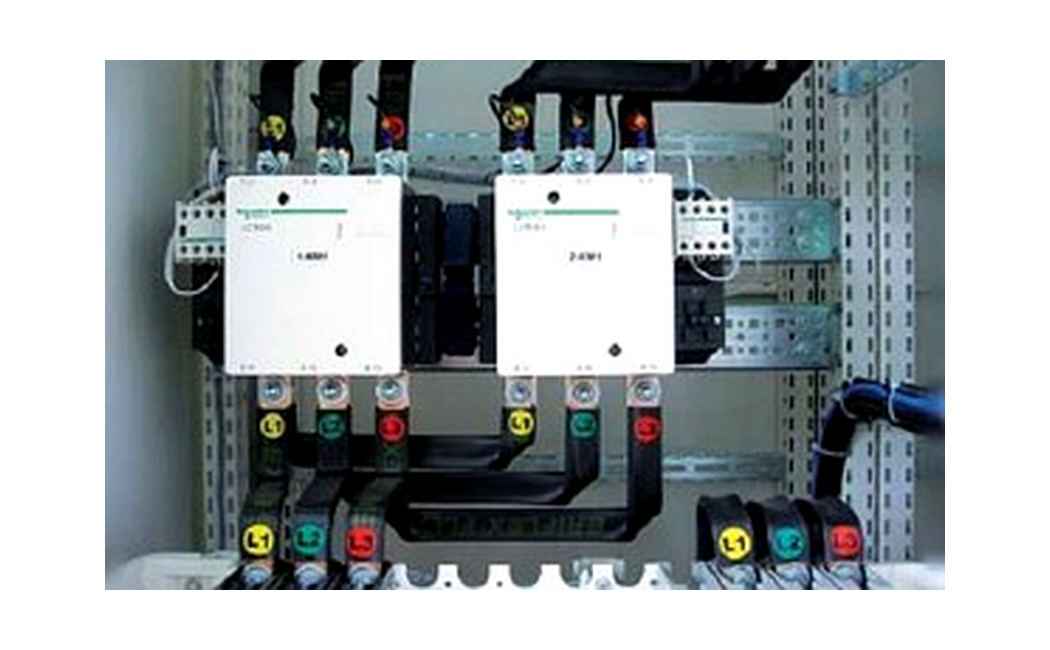
6.1. Contactor-based ATS
A contactor-based ATS is a common budget solution. It usually uses two contactors: one connects the load to the normal incoming supply and the other to the standby supply. Both mechanical and electrical interlocking are essential for safety.
The advantages are low cost and straightforward implementation. However, a contactor arrangement has significant limitations: increased contact wear with frequent switching, the risk of contact sticking, coil heating and dependence on the quality of the interlocking.
An individual contactor may operate quickly, but this should not automatically be regarded as an ATS advantage. Assessment must consider not only device speed, but how the complete system transfers between sources and whether it suits the specific load.
6.2. ATS with a motorised changeover switch
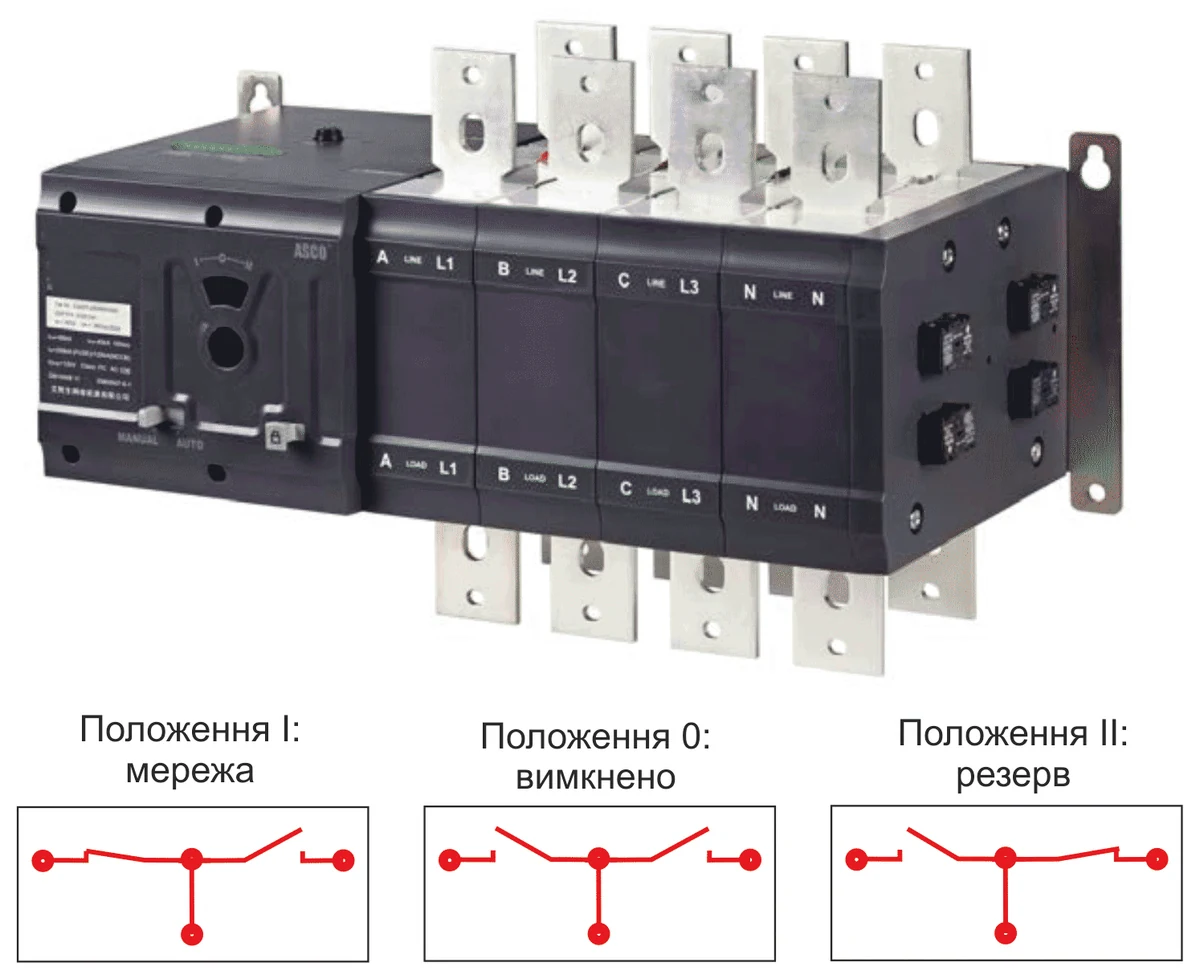
These systems use a load changeover switch with an electric motor operator. The mechanism generally transfers the load physically between two sources and may also include a centre-off position marked 0.
Advantages include a straightforward mechanism, manual operation and an off position for maintenance or emergency load disconnection. Disadvantages include relatively slow transfer and dependence on the motor operator and gearbox endurance.
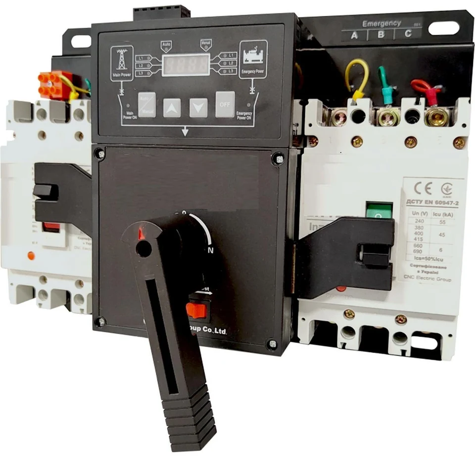
6.3. ATS with motor-operated circuit breakers
In this arrangement, motor-operated circuit breakers perform the switching. It provides both transfer and overload and short-circuit protection for each incoming supply, where these functions are included in the device construction and settings.
The principal advantage is the availability of protective functions. Limitations include a more complex mechanism, the need for precise adjustment of motor operators and interlocks, relatively long transfer times and risks associated with cable-operated or auxiliary-circuit interlocking.
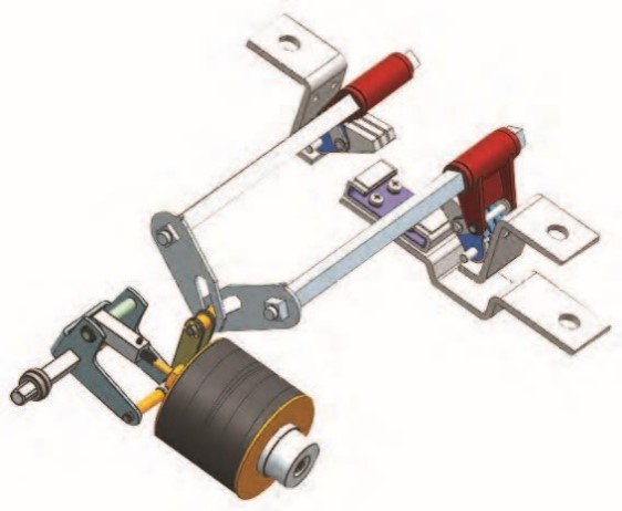
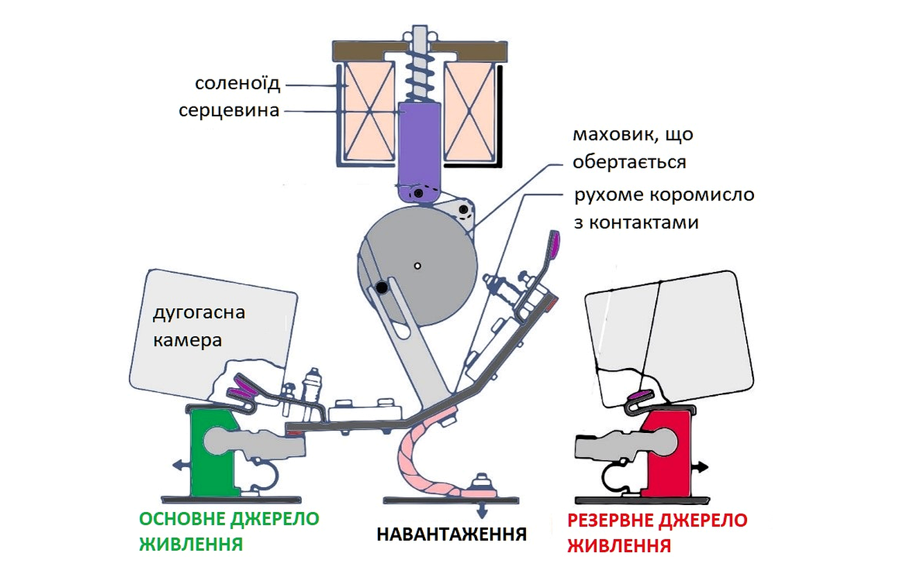
6.4. ATS with a solenoid-operated transfer mechanism
A solenoid-operated transfer mechanism is a dedicated solution for fast load transfer between sources. Mechanical interlocking is built into the power switching assembly itself, while a momentarily energised solenoid drive performs the transfer very quickly.
Advantages include high operating speed, long endurance, protection of the main contacts by arc-extinguishing components, manual transfer capability, compact size and suitability for critical systems. Such solutions are appropriate where reliable transfer mechanics are as important as automatic control.
7. Comparison of typical construction types
| Construction | Speed | Interlocking | Advantages | Limitations |
|---|---|---|---|---|
| Contactors | Depends on the control arrangement | Both mechanical and electrical interlocking required | Low cost, simplicity | Limitations in endurance, operating duty and use in critical systems |
| Motorised changeover switch | Slower | Built into the switch mechanism | Three positions, manual operation, simplicity | Motor operator, gearbox, longer transfer time |
| Motor-operated circuit breakers | Slower | Requires precise adjustment | Protection of incoming supplies, flexibility | Complexity, mechanical adjustments, interlocking risks |
| Solenoid-operated transfer mechanism | Very fast | Built into the power switching assembly | Speed, endurance, arc extinction, manual operation | Higher cost, correct application-specific selection required |
ATS capacity and design margin
Preliminary ATS selection must consider the type of standby source: diesel generator set, inverter, UPS, BESS or portable power station. The supply configuration—single-phase 230 V or three-phase 400 V—and the total connected load power must also be established.
A power margin of 20–30% can be a useful initial guide for simple loads. However, it is insufficient for professional ATS selection: two facilities with the same total power can have very different transfer conditions.
Lighting, sockets, pumps, ventilation, compressors, servers, UPS units and switch-mode power supplies impose different demands on a switching device. In addition to kW or kVA, assessment must cover operational current, starting currents, load characteristics, number of phases, neutral arrangement, standby source type and continuity of supply requirements.
Important: a 20–30% margin is only an initial guide, not a complete ATS sizing calculation. Reliable selection considers the entire power supply system rather than the total connected load alone.
How to recognise reliable ATS information
There is extensive advice on ATS selection online. Some is useful for an initial understanding, but not all material considers the actual operating conditions of standby power systems.
If ATS selection is reduced to total connected load, the number of supply phases and a 20–30% margin, it is only a preliminary guide. Critical facilities also require assessment of the standby source type, load characteristics, starting currents, switching assembly construction, utilisation category, fault withstand capability and transfer logic.
Reliable technical information does not promise a universal solution. It explains why ATS equipment for a private home, generator, UPS, BESS, pumping station or industrial facility may have different constructions and requirements.
When reading ATS articles, consider not only how simple the explanation is, but also whether it addresses standards, utilisation category, switching device type and the operating conditions of the actual load.
Important: an ATS article that reduces selection to power, phases and a margin offers only an initial guide. Correct selection begins with analysis of the complete power supply system, not an advertising figure in a product description.
8. How to select an ATS correctly
Correct ATS selection starts with analysis of the load, power sources and facility operating modes, rather than price or brand. An error can cause standby power to fail precisely when it is needed.
- Number and type of power sources: utility / generator, utility / utility, generator / generator, UPS, BESS or combined arrangements.
- Load type: resistive, inductive, motor or IT loads, compressors, pumps, ventilation, medical or process equipment.
- Utilisation category: AC-33B is an appropriate reference for mixed industrial loads.
- Rated current and short-circuit currents: the ATS must be suitable not only for operational current, but also for the expected fault conditions at the installation point.
- Number of poles: 2P, 3P or 4P, according to the earthing arrangement, neutral and project requirements.
- Transfer time: assess not only device speed, but also the complete transfer sequence, required delays and standby source readiness.
- Manual operation and maintenance: the ATS must provide safe manual transfer, maintenance access and clear status indication.
- Supervisory integration: for critical facilities, an event log, alarm signals, Modbus / Ethernet or other monitoring interfaces are important.
9. ATS controls
An ATS controller must do more than issue a transfer command. It must monitor power source parameters, assess generator readiness, implement delays and generate control signals, interlocks and alarms.
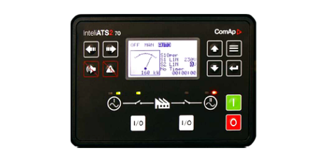
The following control functions are desirable for a professional ATS:
- monitoring of phase voltages, phase imbalance, phase sequence and frequency;
- adjustable operating and recovery thresholds;
- load current measurement and automatic generator overload protection;
- delays for generator starting, transfer, retransfer to the normal source and generator set cool-down;
- prevention of incorrect switching or unintended interconnection of sources;
- manual, automatic and maintenance modes;
- event and alarm log;
- a mimic diagram or indicator lights showing switch position and incoming supply status;
- remote monitoring capability and integration into a supervisory system;
- immunity to interference, voltage dips and supply transients.
10. Practical recommendations
- Do not select an ATS by rated current alone. Load type, short-circuit currents, generator operating duty and transfer time requirements must be considered.
- For critical facilities, solutions with mechanical interlocking built into the transfer mechanism are preferable to arrangements relying solely on external rods or auxiliary contacts.
- For loads with motors, fans, pumps and compressors, starting currents, phase alignment and the possibility of in-phase transfer must be assessed.
- Generator systems must include logic for starting, warm-up, load acceptance, cool-down and retransfer to the utility supply.
- Critical systems require an event log, alarm signalling and remote monitoring.
11. Conclusion
An ATS is power transfer switching equipment, not an auxiliary generator accessory. Its quality determines whether the facility can safely transfer to standby power and return to the utility supply without fault conditions.
Professional ATS selection must be based on standards, utilisation category, switching equipment class, load type, prospective fault currents, power source operating duty and supervisory integration requirements.
Available configurations and selection data are provided on the STAVR industrial ATS page.
Need an ATS selected for your application?
Send a brief description of the power sources, load, current, voltage and operating conditions. We will select a STAVR solution for your facility.