
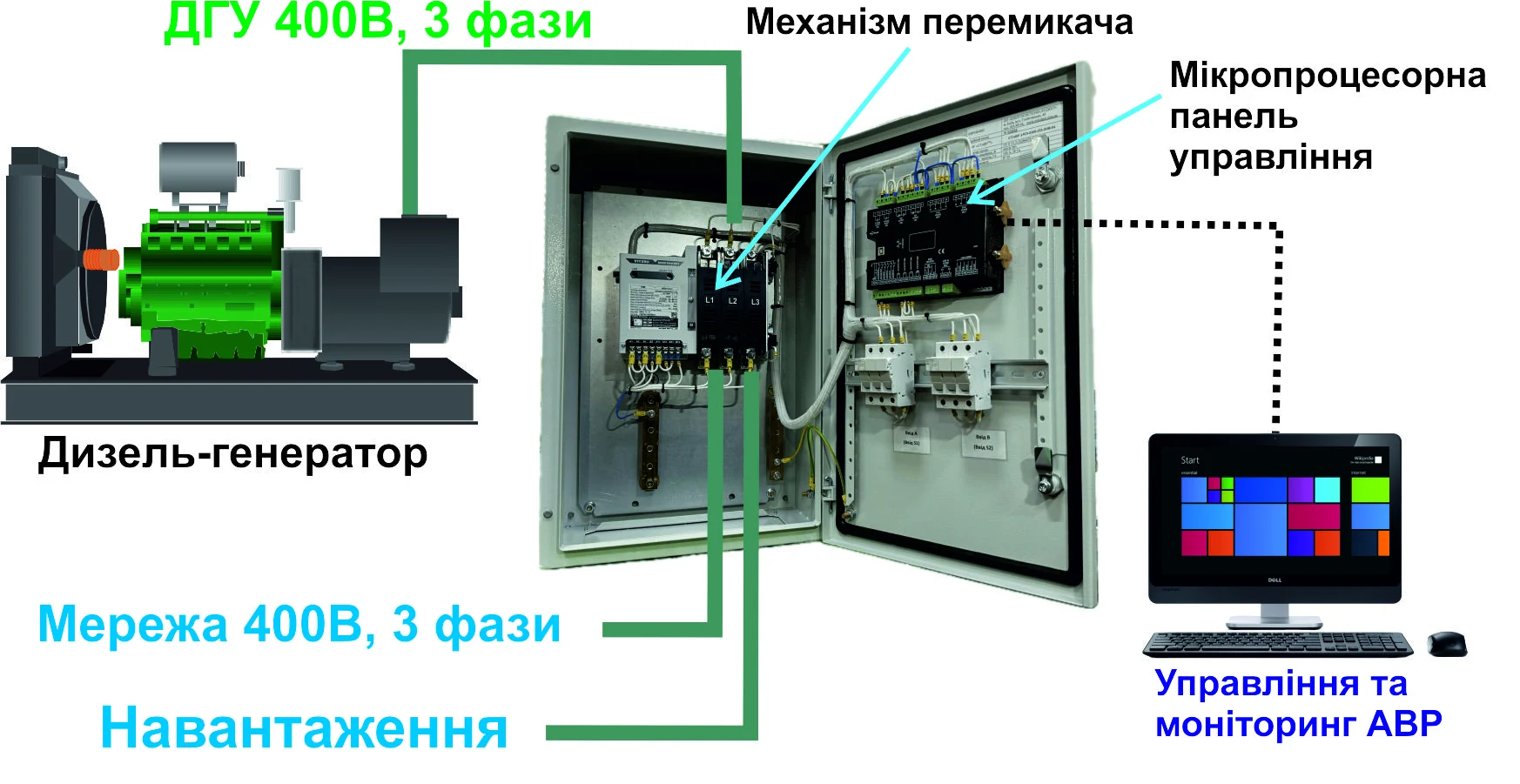
Suppose the calculated load current is 600 A and an 800 A ATS is being considered for the project. Is that enough to make the selection?
The current rating appears to provide a margin. However, it is necessary to establish what the 800 A actually represents: the thermal current of the power switching device, the operational current for a particular load, or the rated current of the complete ATS assembly.
Correct selection requires the load characteristics to be compared with those of the chosen ATS. Voltage, utilisation category and operating conditions matter as well as amperes.
What current must the ATS carry?
The calculated load current is the current the ATS must carry in the intended operating mode of the facility. It is determined by considering the simultaneous operation of loads and which equipment will receive standby power.
For example, if the generator supplies only some of the loads, the load in normal and standby operation will differ. All intended operating modes must be considered when selecting the ATS.
Starting currents and equipment re-energisation after a supply interruption require particular attention. The steady-state current does not describe all the processes that can occur when power is restored.
The selection data therefore comprises more than 600 A: it also includes the load mix and its operating sequence.
What do the current ratings in ATS documentation mean?
Technical documentation may specify several current values. They describe different equipment characteristics and are not necessarily equal.
| Parameter | Practical meaning | What to check |
|---|---|---|
| Ith — conventional thermal current | The current a device can carry continuously under the conditions specified by the standard without an unacceptable temperature rise | Do not treat Ith as a universal operational current for every load |
| Ie — rated operational current | The current at which the manufacturer declares device operation for a specified voltage, utilisation category and operating conditions | Find Ie for the required voltage and load characteristics |
| Ue — rated operational voltage | The voltage to which the declared operating characteristics apply | Ensure that the Ie value is specified for the relevant supply voltage |
| Rated current of the complete ATS assembly | A characteristic of the complete assembly, taking account of the power switching devices, busbars, connections and their operating conditions within the enclosure | Check the characteristics of the complete assembly, not only the installed power switching device |
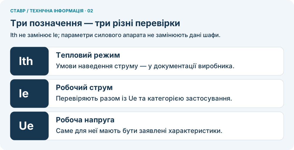
Figure 2. Ith, Ie and Ue: three separate checks.
The conditions under which Ith is specified must be checked in the manufacturer documentation. Installation in an enclosure may change the thermal conditions, so the permissible current of the complete assembly must be verified separately. Schneider Electric explanation of thermal current.
Thus, Ith = 800 A does not mean Ie = 800 A for every load. Likewise, the statement that an 800 A power switching device is installed does not by itself establish the rated current of the complete ATS assembly.
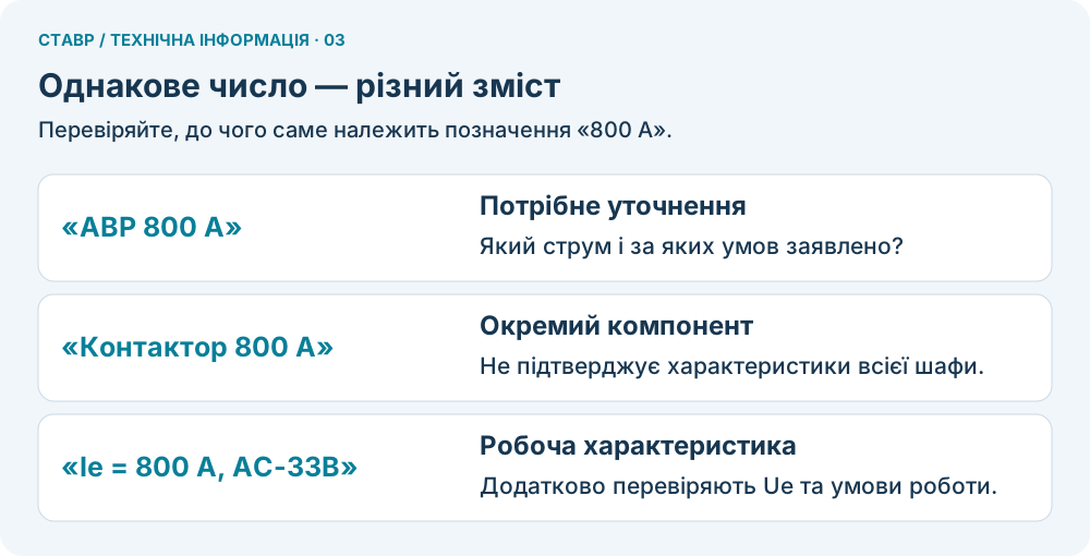
Figure 3. Three different meanings of an 800 A designation.
Why is the utilisation category important?
The utilisation category defines the load characteristics and switching conditions for which the operational current Ie is declared.
Utilisation categories for transfer switching equipment are addressed in IEC 60947-6-1. The common categories can be explained in practical terms as follows:
| Utilisation category | Load characteristics |
|---|---|
| AC-31B | Resistive or slightly inductive load |
| AC-32B | Mixed resistive and inductive load, including moderate overloads |
| AC-33B | Motor loads or mixed loads including electric motors |
The presence of motors, pumps, compressors or UPS equipment is a reason to consult the utilisation category table rather than rely on an 800 A label.
However, specific equipment should not automatically be assigned to a category solely by its name. The actual electrical characteristics of the load matter, including starting behaviour and its response when power is restored.
The suffix B denotes applications with the infrequent switching typical of many ATS systems. If frequent switching is intended, the category and endurance must be checked for suitability. Socomec technical guide.
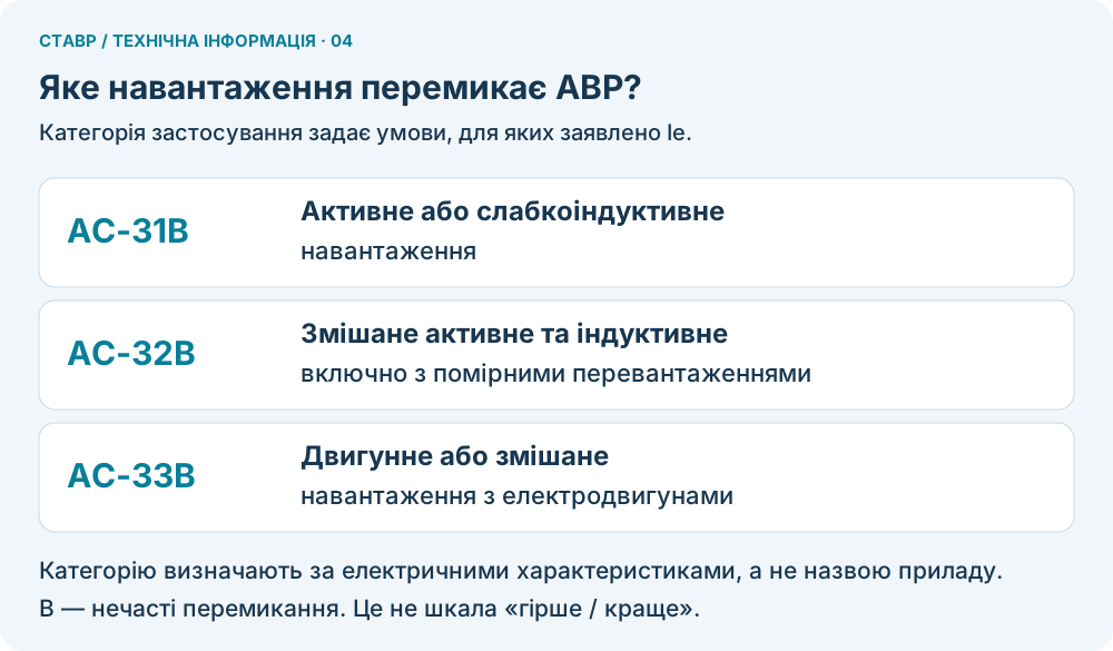
Figure 4. Categories AC-31B, AC-32B and AC-33B.
The practical selection question is: what operational current Ie does this ATS have at the required voltage and utilisation category?
How to read rated characteristics: the Socomec ATyS example
The difference between thermal and operational current is clearly illustrated by the Socomec ATyS p.
In manual 542001G, the manufacturer lists the thermal current Ith at 40 °C separately from the operational currents Ie for different utilisation categories at 415 V AC.
Selected values from this table are shown below.
| Ith | Ie AC-31B | Ie AC-32B | Ie AC-33B |
|---|---|---|---|
| 800 A | 800 A | 800 A | 800 A |
| 1250 A | 1250 A | 1250 A | 1000 A |
| 1600 A | 1600 A | 1250 A | 1000 A |
| 2500 A | 2500 A | 2000 A | 1250 A |
| 3200 A | 3200 A | 2000 A | 1250 A |
Source: Socomec ATyS p, manual 542001G. These values apply to the stated version and conditions; the documentation for the specific device must be checked.
For example, a device with Ith = 1600 A has:
- Ie = 1600 A for AC-31B;
- Ie = 1250 A for AC-32B;
- Ie = 1000 A for AC-33B.
This is not a design weakness, but a correct declaration of device capability for different load characteristics.
If a project requires an operational current of 1200 A for AC-33B, this device does not meet the Ie requirement: the manufacturer declares 1000 A in the required category despite a thermal current of 1600 A.
In a ratings table, therefore, first locate the required voltage and utilisation category, then compare the corresponding Ie with the calculated load current.
Contactor-based ATS: permissible current for different loads
A contactor-based ATS is an established and widely used technical solution when the characteristics of the complete assembly match the specific load.
In its catalogue of complete MS ACOC contactor-based ATS assemblies, Mertech specifies different rated operational currents Ie for categories AC-31B and AC-33B:
| Ie for AC-31B | Ie for AC-33B |
|---|---|
| 100 A | 65 A |
| 250 A | 150 A |
| 400 A | 320 A |
| 800 A | 630 A |
Source: official Mertech catalogue — Automatic Changeover Panels, page 2.
The manufacturer declares these currents for different utilisation categories of the complete MS ACOC contactor-based ATS. For example, a version rated Ie = 800 A for AC-31B has Ie = 630 A for AC-33B. These are characteristics of the complete ATS, not individual contactor ratings assumed to apply to the assembly.
AC-3 for a contactor is not AC-33B for a complete ATS
AC-1 and AC-3 refer to contactor characteristics under IEC 60947-4-1.
AC-31B, AC-32B and AC-33B are utilisation categories for the complete ATS under IEC 60947-6-1.
Therefore, the AC-3 rating of an individual contactor cannot automatically be equated with AC-33B for a complete ATS. Installing particular contactors does not establish the utilisation category of the entire assembly.
For selection, it is essential to check the operational current and category declared and verified by the manufacturer for the complete ATS.
ATS switching capacity
An ATS must not only carry its rated current continuously, but also reliably make and break the load current. Switching currents can significantly exceed operational current Ie, particularly where electric motors are present.
IEC 60947-6-1 specifies different switching capacity test conditions depending on the ATS utilisation category.
| Utilisation category | Making test current |
|---|---|
| AC-31A / AC-31B | 1,5 × Ie |
| AC-32A / AC-32B | 3 × Ie |
| AC-33A / AC-33B | 10 × Ie |
The suffix A denotes applications with frequent switching; B denotes infrequent switching. The ATS switching endurance requirements differ accordingly.
These values do not mean that the ATS can carry such currents continuously or is intended to interrupt short-circuit currents.
The utilisation category therefore determines not only the load characteristics, but also the ATS switching capability and endurance requirements.
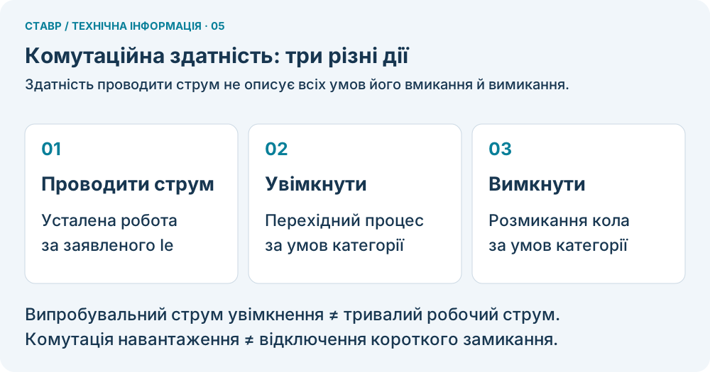
Figure 5. Carrying, making and breaking current.
ATS short-circuit withstand capability
The rated operational current Ie defines the permissible ATS load under normal conditions. During a short circuit, however, the current can be many times the rated current, so it is important to know the fault current that the device can withstand.
Regardless of whether the utilisation category is AC-33A or AC-33B, ATS short-circuit withstand capability must be checked separately.
Standard IEC 60947-6-1 contains tables of short-circuit test currents according to rated operational current Ie.
Short-circuit test currents under IEC 60947-6-1
| Rated operational current Ie | Short-circuit test current |
|---|---|
| Up to and including 100 A | 5 kA |
| Over 100 A up to 250 A | 10 kA |
| Over 250 A up to 500 A | 18 kA |
| Over 500 A up to 800 A | 30 kA |
| Over 800 A up to 1300 A | 42 kA |
| Over 1300 A | By agreement between the manufacturer and the user |
Values from harmonised Table 6 of IEC 60947-6-1 for testing under the corresponding conditions. They are not automatically guaranteed characteristics of every ATS.
It is important to distinguish two parameters in the manufacturer documentation:
- Icw — the short-circuit current that the ATS withstands for a specified duration.
- Iq — the prospective short-circuit current permitted when the protective device specified by the manufacturer is used.
Practical example: Schneider Electric TransferPacT
For an 800 A TransferPacT in category AC-33B, the manufacturer specifies:
- Icw = 25 kA for 0.1 s;
- Iq up to 200 kA with the appropriate fuse.
This illustrates the difference between the inherent short-time withstand capability of an ATS and its conditional short-circuit current with suitable protection. Source: IECEE CB certificate for TransferPacT TA80/TR80.
For ASCO 7000, documentation under US standard UL 1008 uses the WCR (Withstand and Closing Rating). This should not be directly equated with Iq under IEC. ASCO technical material on WCR.
Conclusion: a short-circuit current value in kiloamperes must be considered together with the withstand duration and protection conditions.
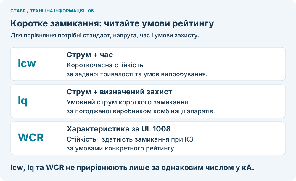
Figure 6. Icw, Iq and WCR: different assessment conditions.
What else must be checked besides operational current?
Compliance with the required Ie is necessary, but is not the only condition for correct selection.
- Electrical and mechanical endurance. The number of on-load operations and the number of mechanical operations are different characteristics. They must suit the expected transfer frequency.
- Installation conditions and temperature. Enclosure installation, cooling and temperature must match the conditions under which the characteristics are declared.
What must be checked before final ATS selection?
Before final selection, the project requirements must be compared with the following data:
| What is checked | What to look for |
|---|---|
| Rated current of the complete ATS | Whether the declared value applies to the entire assembly |
| Ie at the required Ue and utilisation category | Whether the operational current matches the load under the required conditions |
| Short-circuit characteristics | Current values, duration and protection requirements |
| Endurance | Electrical and mechanical endurance for the intended duty |
| Installation conditions | Temperature limits, cooling and possible current derating |
| Documentary evidence | Whether the declared characteristics apply to the selected version |
For the initial example of a 600 A load, this means that an 800 A ATS can be considered suitable in terms of current only after confirming the required Ie at the relevant Ue, utilisation category and actual operating conditions.
How ATS construction affects its characteristics
An ATS based on contactors, circuit breakers, motorised load switches or dedicated solenoid-operated switching devices can be the correct solution, depending on the application conditions.
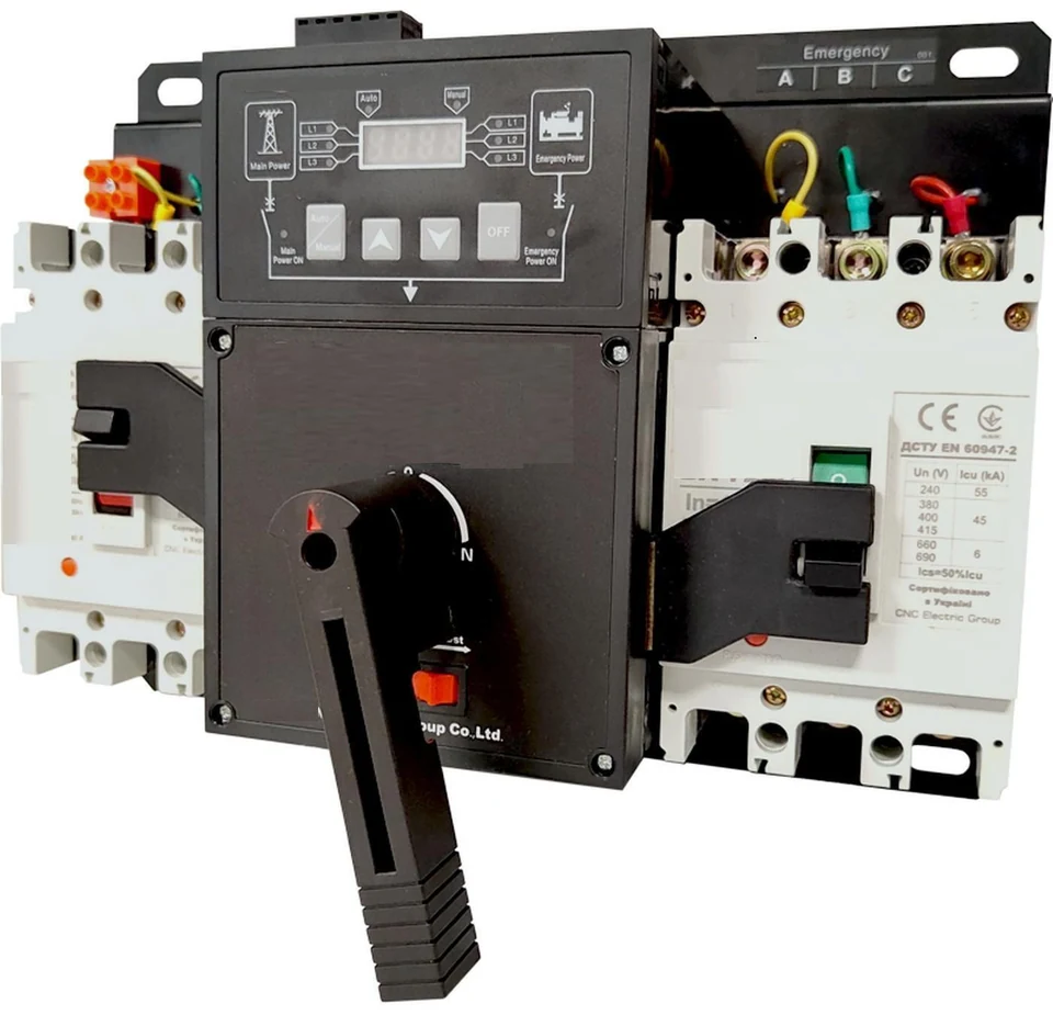
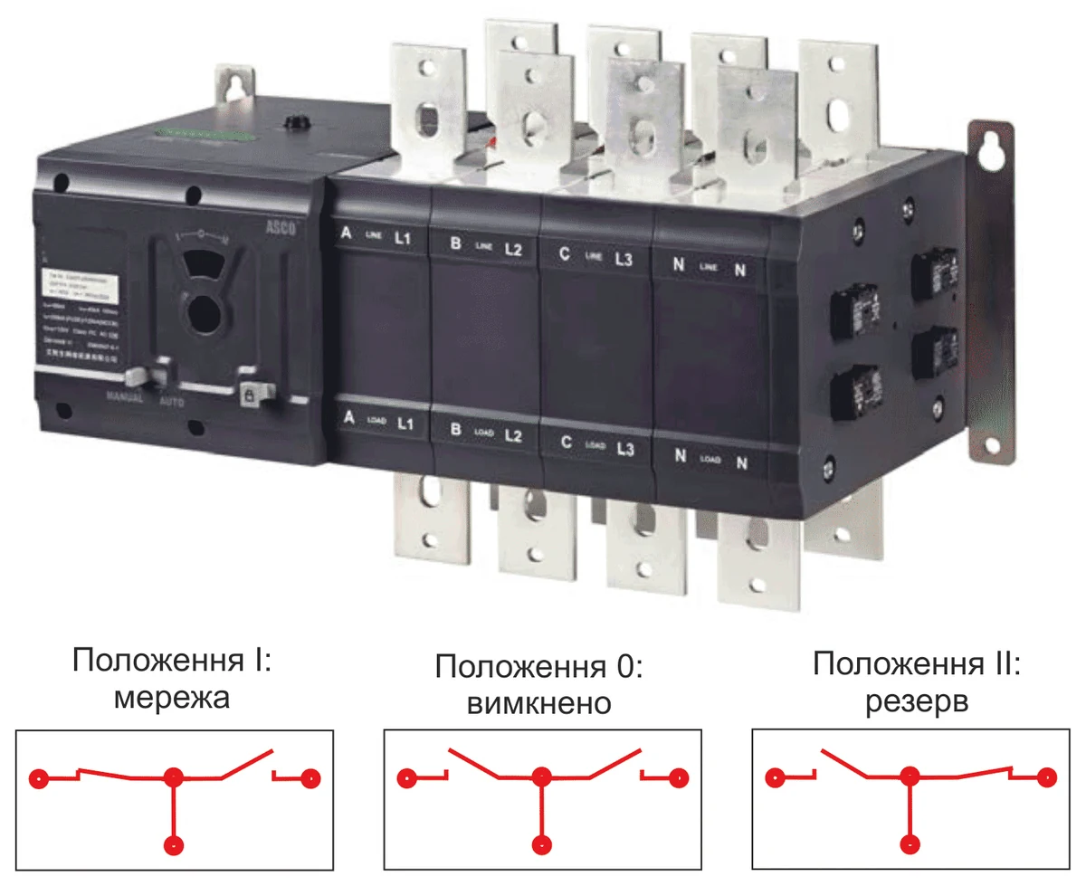
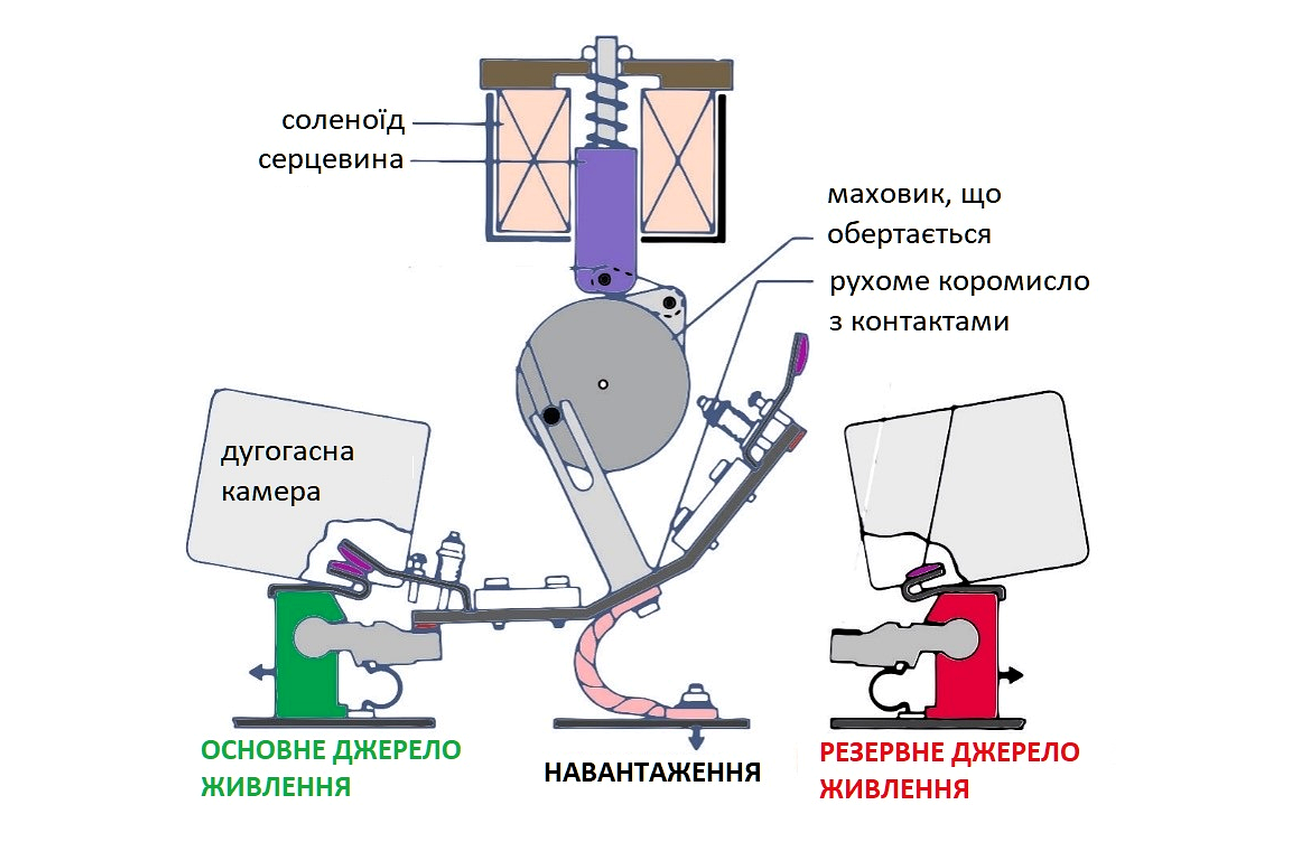
ATS construction is fundamentally important. It affects transfer speed, switching capability, mechanical and electrical endurance, short-circuit withstand performance and operating characteristics.
A particular construction may offer significant advantages for a specific application. These advantages must be assessed against the verified technical characteristics of the complete ATS.
ATS construction is selected according to technical requirements, operating conditions and economic suitability, considering not only the initial cost but also costs throughout the service life.
Two ATS devices with the same stated current, such as 800 A, therefore do not necessarily have the same capabilities.
The comparison must be between current ratings under identical application conditions, not simply between ampere figures.