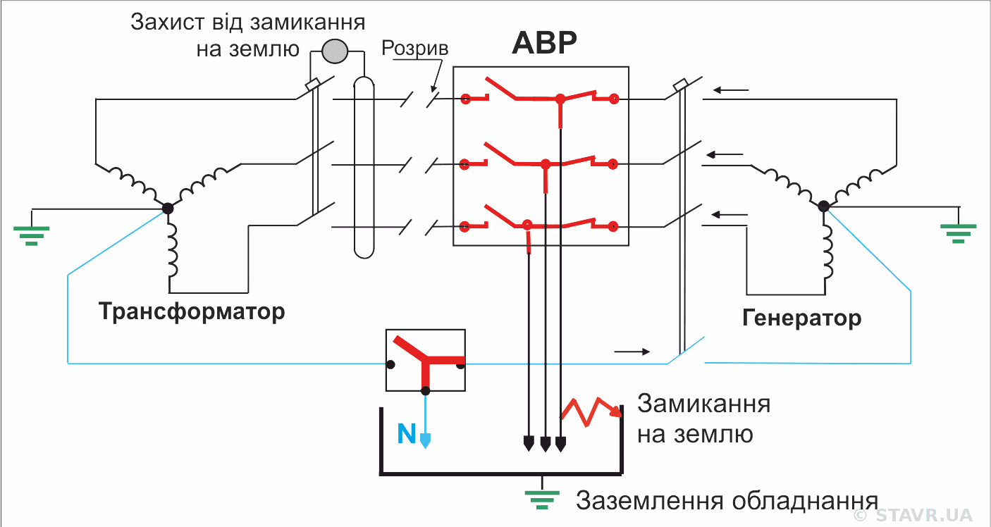
When a three-pole ATS is sufficient and when four poles are necessary. Selection is determined by the power-supply arrangement, earthing system and protective-device operation, rather than habit or switch price.
When is 3P sufficient, and when is 4P required?
One of the most common questions when designing standby power systems is whether to use a three-pole or four-pole ATS. At first glance, the only difference is an additional pole for the neutral. In practice, this decision can affect correct earth-fault protection operation, the earthing arrangement, safe transfer between utility and generator, and the operation of single-phase loads.
Key point: there is no universal rule to always use 3P or always use 4P. The correct solution depends on the specific facility arrangement.
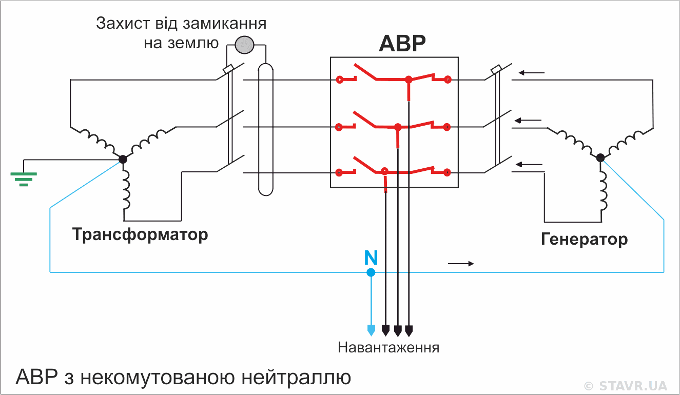
ATS with a solid neutral
In a three-pole ATS, only the phase conductors are switched. The neutral conductors of the normal and standby sources remain permanently connected.
This arrangement is widely used in industrial electrical installations and is technically appropriate in many cases. Its construction is simpler, it has fewer power contacts and it does not momentarily interrupt the neutral during transfer.
However, both sources remain electrically connected through the neutral conductor even after the phases have been transferred. In this arrangement, the normal and standby sources operate within a common earthing system.
If the generator neutral is permanently connected to the utility neutral, it should generally not have an additional separate connection to PE. Otherwise, parallel current paths may arise through neutral and protective conductors.
The suitability of a 3P ATS must therefore be checked with regard to the generator neutral earthing arrangement, the presence of multiple simultaneous N–PE bonding points and the operating principles of the protective devices.
ATS with a switched neutral
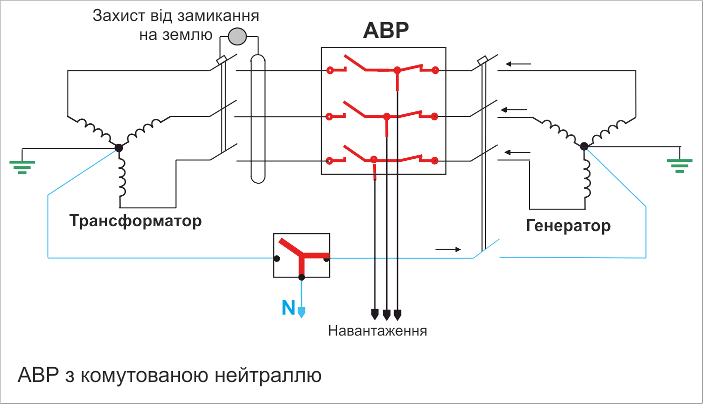
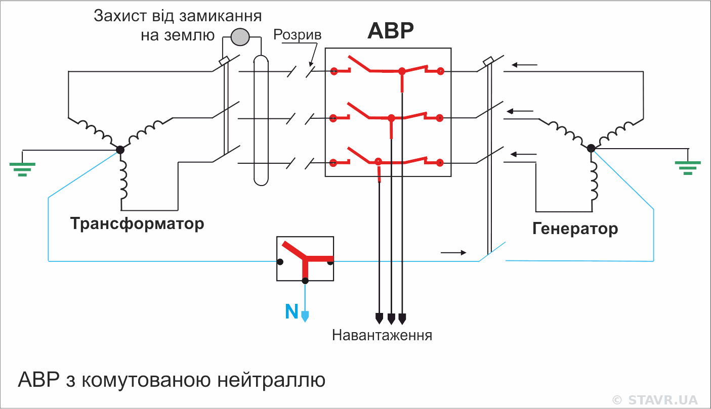
In a four-pole ATS, the neutral conductor is switched together with the phase conductors. In each steady ATS position, the load is connected only to the neutral of the active source.
This arrangement is used where the live conductors and neutrals of the normal and standby sources must be separated, parallel neutral current paths eliminated, or a defined earth-fault return path provided.
With a 4P ATS, the generator can operate as a separate source with its own defined N–PE bonding point. The PE protective conductors and equipotential bonding system remain common.
Advantagethe neutrals of the two sources do not remain permanently interconnected.
Requirementthe neutral-pole operating sequence must suit the circuit arrangement and load characteristics.
Important: using a 4P ATS does not automatically make a system safer. The fourth pole must be justified by the earthing arrangement and protection scheme.
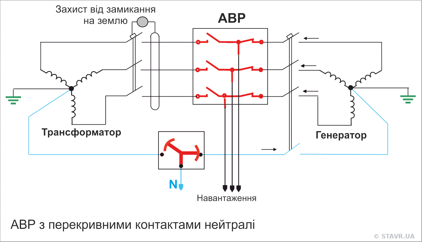
ATS with overlapping neutral contacts
Unwanted transient voltages that may occur during neutral switching can be reduced by using an ATS with overlapping neutral contacts.
These contacts follow the make-before-break principle: the new source neutral closes before the previous source neutral opens. For a brief interval, the two source neutrals are connected together, while the phase contacts continue to follow the conventional open-transition sequence.
Contact overlap maintains neutral continuity, reduces the risk of transient overvoltages across single-phase loads and supports correct earth-fault protection operation. Overlapping neutral contacts connect the neutrals of both sources only briefly, usually for up to 100 ms. With properly coordinated and set protection, this interval is insufficient to cause tripping.
The neutral as a current-carrying conductor and the consequences of damage
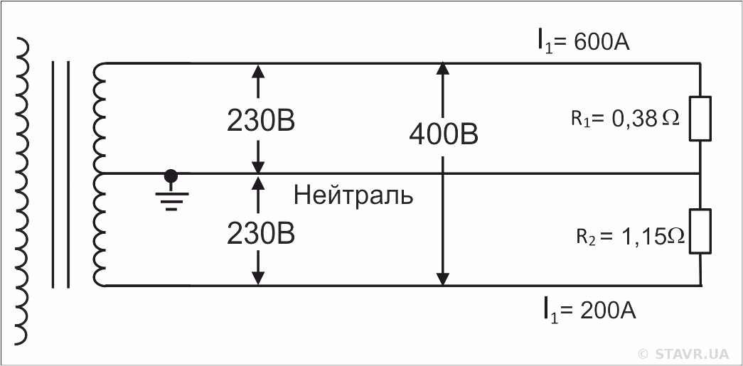
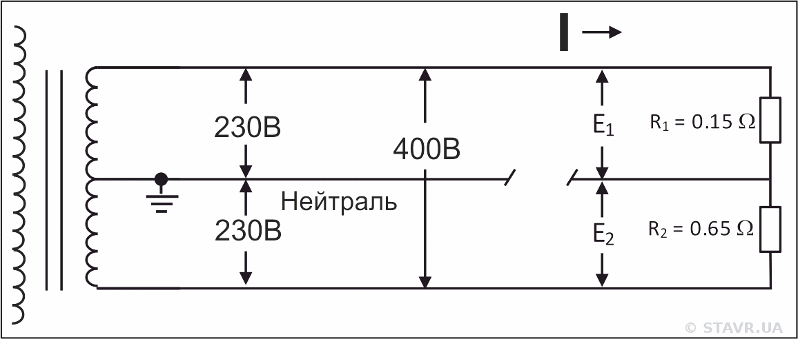
In a three-phase, four-wire system, the neutral conductor provides a path for unbalanced current and maintains a defined potential at point N. Damage to it drastically changes the operating conditions of single-phase loads.
With an intact neutral, unbalanced current returns to the source and phase-to-neutral voltages remain defined.After N is broken, the phase-to-phase voltage is divided between the single-phase loads according to their impedances.
In a three-phase, four-wire system with unbalanced single-phase loads, unbalanced current flows through the intact neutral conductor. This is normal system operation: the neutral maintains the potential of point N relative to the source, so even a substantial neutral current does not itself cause phase-to-neutral voltage imbalance.
If the neutral conductor is broken, the potential of the common point of the single-phase loads shifts. In a simplified case, the loads form a series circuit between phases, and the 400 V phase-to-phase voltage is divided between them according to their impedances. This causes a dangerous imbalance in phase-to-neutral voltages.
As a result, some loads may receive a dangerously high voltage, while others receive a voltage too low for normal operation.
Important: neutral current and phase-to-neutral voltage imbalance are different phenomena. Voltage imbalance occurs when the neutral is broken or its circuit has significant contact resistance.
Damage to the standby source neutral conductor
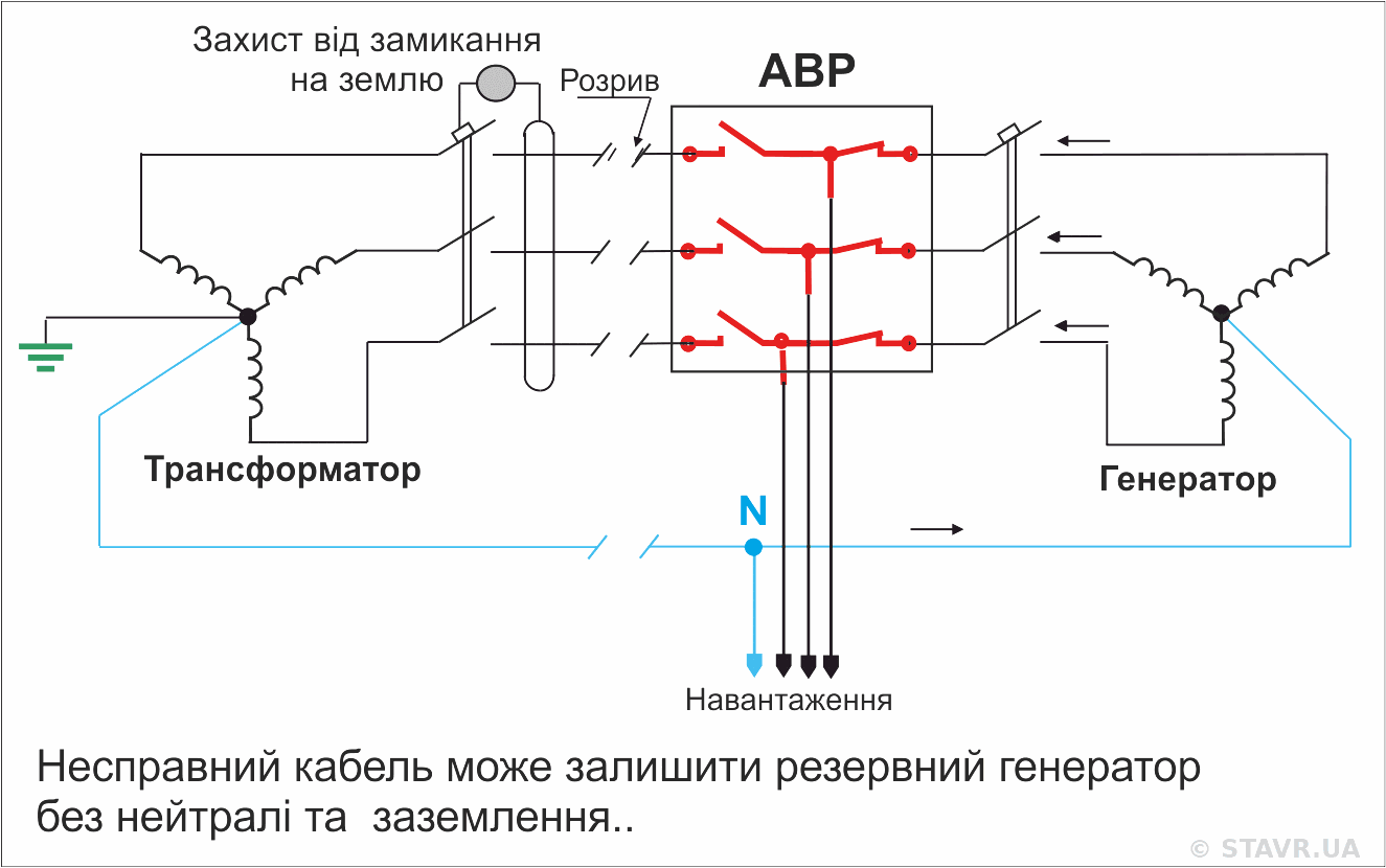
In a solid-neutral arrangement, the condition of the generator neutral conductor and its cable must be assessed together with the entire earthing system. Damage to N or an incorrect N connection can alter the intended fault-current path and the operating conditions of the standby source.
Earth-fault protection
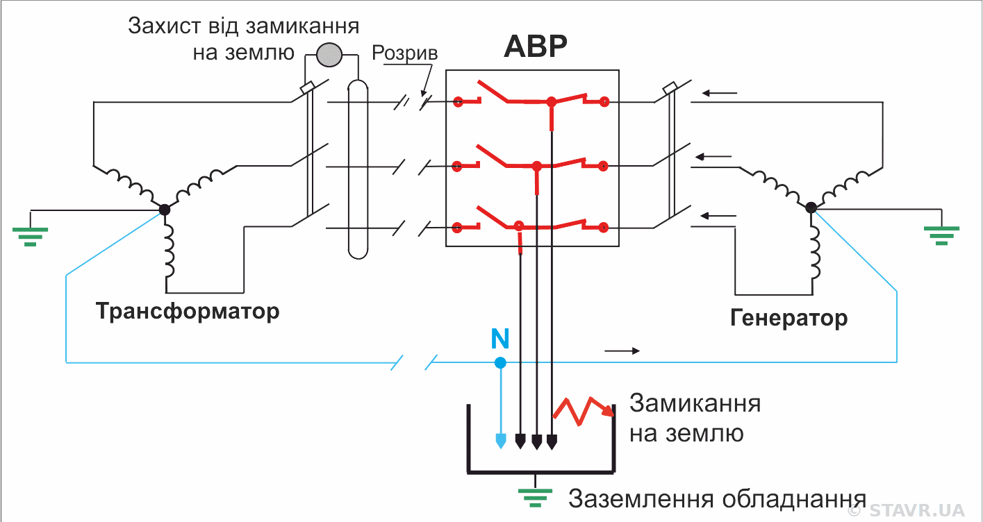
Correct protection operation requires a defined fault-current return path to the active source. With multiple simultaneous neutral-to-PE bonding points and a common neutral, current may divide between parallel paths. This can affect the sensitivity or selectivity of certain protection schemes.
Three-pole ATS — solid neutral
The neutrals of the normal and standby sources remain connected. Depending on the location of the current transformers and earthing points, part of the fault current may flow outside the monitored circuit, potentially causing incorrect protection operation.
Four-pole ATS — switched neutral
The active source neutral is switched together with the phase conductors. With correctly implemented earthing, a defined N–PE bonding point and correctly positioned current transformers, the fault current can return along its intended path and be fully included in the protection measurement.
The final solution must account not only for the ATS type, but also for current-transformer locations, the residual-current measurement principle, earthing points and each source's operating modes.
What to check before selecting a 3P or 4P ATS
Before selecting a neutral-switching arrangement, check:
which earthing system is used for the utility supply and generator, and where the N–PE bonds are located;
whether parallel current paths arise through neutral and protective conductors;
how earth-fault protection operates when supplied from each source;
the neutral-pole operating sequence during automatic and manual transfer;
how a momentary neutral interruption may affect single-phase loads;
whether the selected arrangement matches the facility's actual configuration, rather than a standard solution from another project.
What to avoid when selecting an ATS
do not copy a 3P or 4P solution from another facility without checking its earthing arrangement;
do not add a generator N–PE bonding point in an arrangement with a common solid neutral;
do not assume that a 4P ATS is automatically safer than a 3P ATS;
do not change the neutral-switching arrangement without rechecking protection operation in every mode.
Practical conclusion
A 3P ATS is appropriate when the utility and generator neutrals remain common, the generator has no additional separate N–PE bond, and protection operation has been verified for both sources.
A 4P ATS is generally required when the generator operates as a separately earthed source with its own defined N–PE bonding point, or when the source neutrals must be separated.
The final decision is based on the facility's single-line diagram after checking the earthing system, fault-current paths and protection operation in both utility and standby modes.
Note: this material draws on practical experience in designing, retrofitting and maintaining standby power systems. All diagrams are original STAVR illustrations.