ATS retrofit

ATS retrofitand modernisationwithout unnecessary enclosure replacement

If the power switching equipment in an ATS or LV switchboard still has service life remaining, replacing the entire enclosure may be unnecessary. It often makes more sense to retain suitable equipment and upgrade the controls, transfer logic, interlocks, indication and monitoring.

We start with a technical assessment: what can safely remain, what must be replaced and what needs to be added for reliable operation.

The aim of a retrofit is to restore predictable ATS operation: safe source transfer, a clear manual mode, event tracking and fewer unexpected faults for operating staff.

Typical tasks
The solution

Modernisation starts with diagnostics and a defined scope of work

The main concern in an old ATS is often the unknown state of its controls: added relays, undocumented jumpers, the condition of interlocks, the response to loss of a source and the risk of backfeed. The first step is a systematic engineering assessment.

RetainA suitable enclosure, selected busbars, cable entries, protective devices or power switching equipment, subject to inspection.
ReplaceAn obsolete controller, unreliable auxiliary relays, inadequate indication or a worn transfer switch.
AddMonitoring, an event log, volt-free contacts, a maintenance bypass, position feedback and alarm signals.
Avoid new risksCheck interlocks, source priorities and return-transfer scenarios before connecting additional power sources.
Before / After

What matters is the improvement in operation

Before-and-after comparisons show the purpose of a retrofit: removing weak points and making the ATS easier to operate, diagnose and maintain. The goal is to restore control of the system and its behaviour.

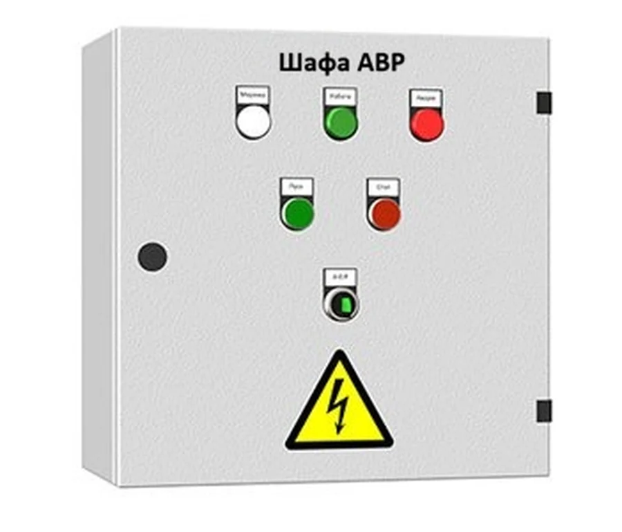
Old ATS enclosure with minimal indication before retrofit

Before Uncertain control status

Limited indication, unclear source status, no event log and difficult fault diagnosis.
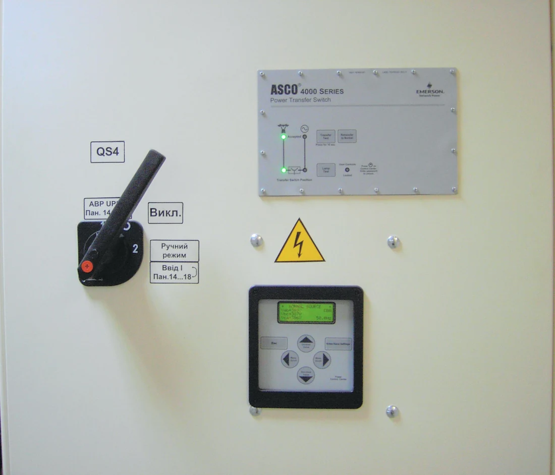
ATS door with controller, indicators and manual selector after retrofit

After New logic and visibility

An ATS controller, clearly defined delays, source priorities, alarms, a maintenance bypass and provision for supervisory monitoring.

Controller capabilities →
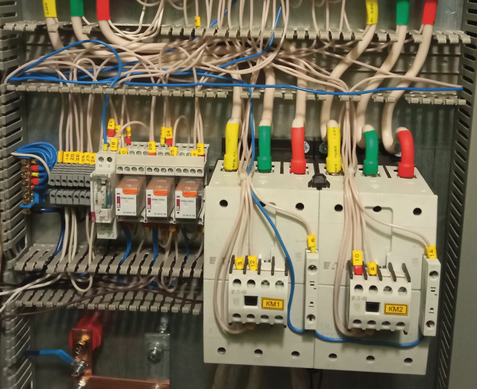
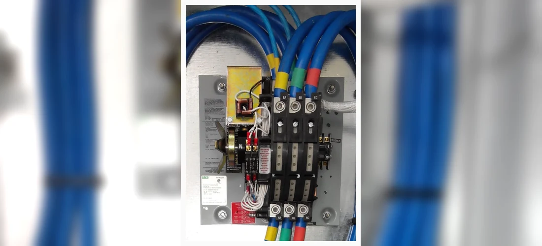
Old ATS power switching equipment with contactors and circuits awaiting inspection

Before Risks in the power circuit

Contacts, terminals, busbars, interlocks and the utilisation category need checking, especially after years of operation under load.

Upgraded ATS power switching assembly after retrofit

After Verified transfer operation

The power switching equipment is assessed for current rating, service life, interlocks and duty. The circuit is updated to follow a clear, safe operating sequence.

Photos can be replaced with examples from the customer's own facilities. The page is arranged in before-and-after pairs so that each retrofit case can be presented clearly and accurately.
When it is needed

An ATS retrofit is needed when the existing equipment no longer meets the facility's requirements

An old ATS may still transfer power while no longer matching the facility's actual configuration. A generator, UPS or BESS may have been added, bus sections changed, or new monitoring and maintenance requirements introduced. These changes call for a coordinated engineering solution.

Obsolete controlsNo event log, clear indication, controller support or adequate description of the operating sequence.
Years of circuit modificationsAdditional relays, jumpers, auxiliary contacts or power sources installed without a coordinated design.
Power equipment needs assessmentThe transfer switch, busbars, terminals, interlocks, utilisation category and signs of overheating need checking.
Maintenance bypass requiredCritical loads need to remain supplied while the ATS assembly is serviced or tested.
Engineering approach

Inspect first. Then decide what to retain, replace or add

A retrofit starts by documenting the actual condition of the enclosure and equipment. This assessment determines the work required on the enclosure, power circuit, controls, signals, bypass and monitoring.

May be retained

  • A serviceable ATS or LV switchboard enclosure.
  • Selected busbars and cable connections.
  • Protective devices, subject to inspection.

Common replacements

  • An obsolete ATS controller.
  • Auxiliary relays and disorganised control wiring.
  • A transfer switch that no longer meets the requirements.

Typical additions

  • Monitoring and an event log.
  • Signals for a supervisory control system.
  • A maintenance bypass or test mode.
1. AssessmentPhotos, drawings, power switching equipment, interlocks and power sources.
2. Engineering solutionDefine what to retain and replace, and which signals and operating modes to add.
3. InstallationAssembly, labelling, connections and maintenance bypass checks.
4. CommissioningTransfer operation, delays, interlocks, alarms and monitoring.
The result

A retrofitted ATS should be straightforward to operate

The goal is a manageable system: staff understand what the ATS is doing, why it is doing it, which signals it provides and how to maintain the equipment safely.

Clear operating sequenceDocumented normal operation, fault conditions, return to the preferred source and transfer inhibit conditions.
Verified interlocksChecks of switch position, power sources, backfeed prevention and protection against operator errors.
Event monitoringStatus signals, alarms, an event log or volt-free contacts for supervisory monitoring.
MaintainabilityLabelled circuits, accessible components, a maintenance bypass and fewer undocumented jumpers.
Typical tasks

Typical ATS retrofit tasks

Select a task to see a short description of the corresponding solution below.

Control and monitoring

Controller, signals and event log.

Transfer logic

System architecture without publishing detailed control algorithms.

Power switching equipment

Inspect or replace the ATS transfer switch.

Maintenance bypass

Service the ATS with less downtime.

System expansion

Add a generator, UPS, BESS or second incomer.

Upgrading control and monitoring

A controller replacement is most useful when combined with clear indication, status signals, an event log and well-defined service modes.

  • Check utility and generator signals, switch position feedback and alarm inputs.
  • Upgrade indication, volt-free contacts, ready signals and alarms.
  • Add an event log for operations and incident analysis.
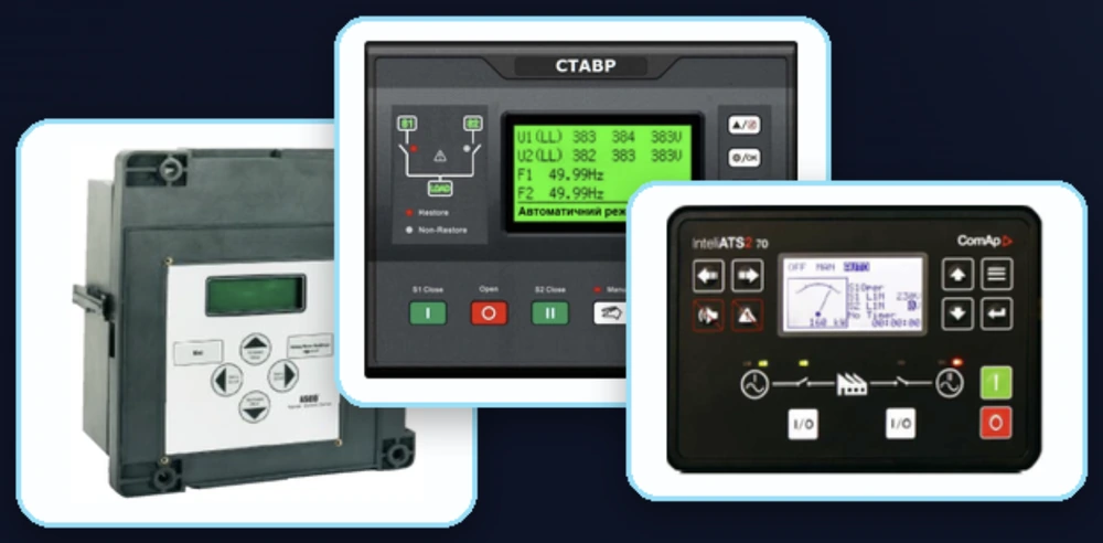
Controllers and monitoring for an ATS retrofit
The controller, indication and monitoring form a single control system. It should transfer power and also help staff understand what has happened.

Revising transfer logic

Sometimes the problem lies in the operating logic of the whole system. Two incomers, load sections, a generator, transfer inhibit conditions, return to utility and manual modes must work together.

  • Define operating modes around the customer's requirements.
  • Check that sources, bus sections and switching assemblies interact safely.
  • Detailed algorithms, settings and interlock diagrams remain in the project documentation.
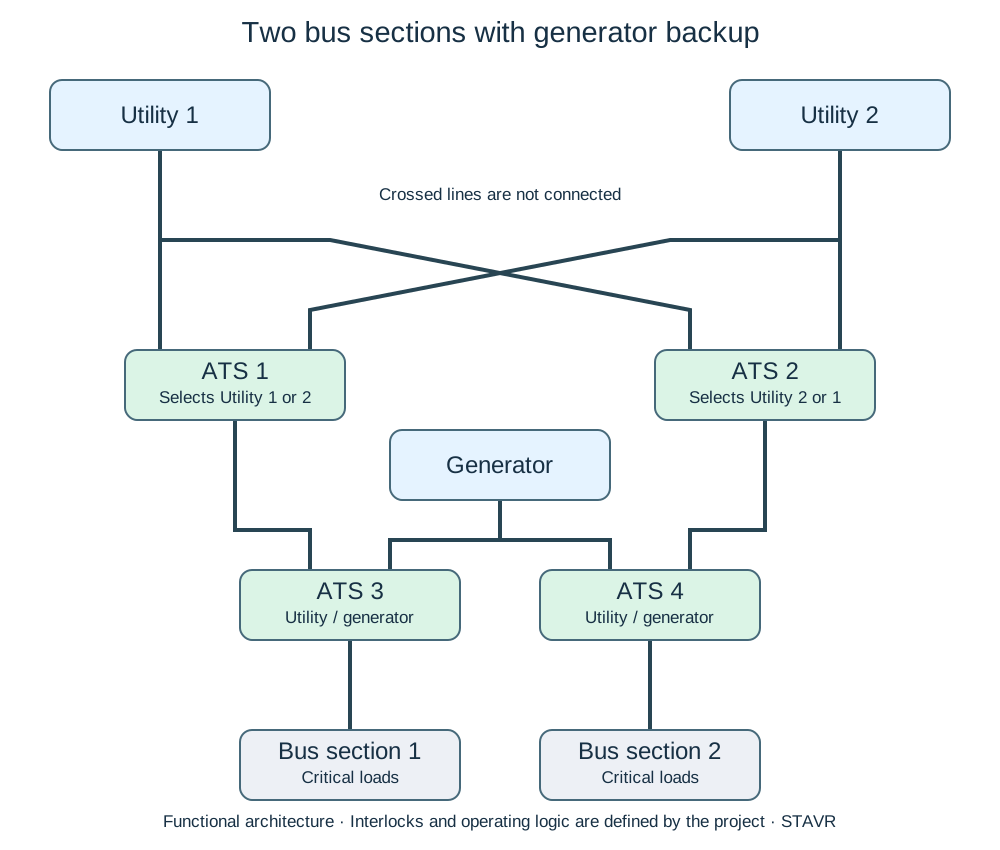
STAVR ATS concept diagram for two utility incomers, a generator and two critical-load bus sections
The diagram shows the system architecture: sources, bus sections, generator and switching assemblies. Internal control algorithms, interlocks and settings are not published.

Inspecting or replacing power switching equipment

If the power switching equipment is worn, has an unsuitable utilisation category or shows signs of overheating, the retrofit must address more than the controller.

  • Check contacts, terminals, busbars and signs of thermal damage.
  • Assess suitability for the current rating, number of poles and load duty.
  • Replace the transfer switch or revise the circuit where necessary.
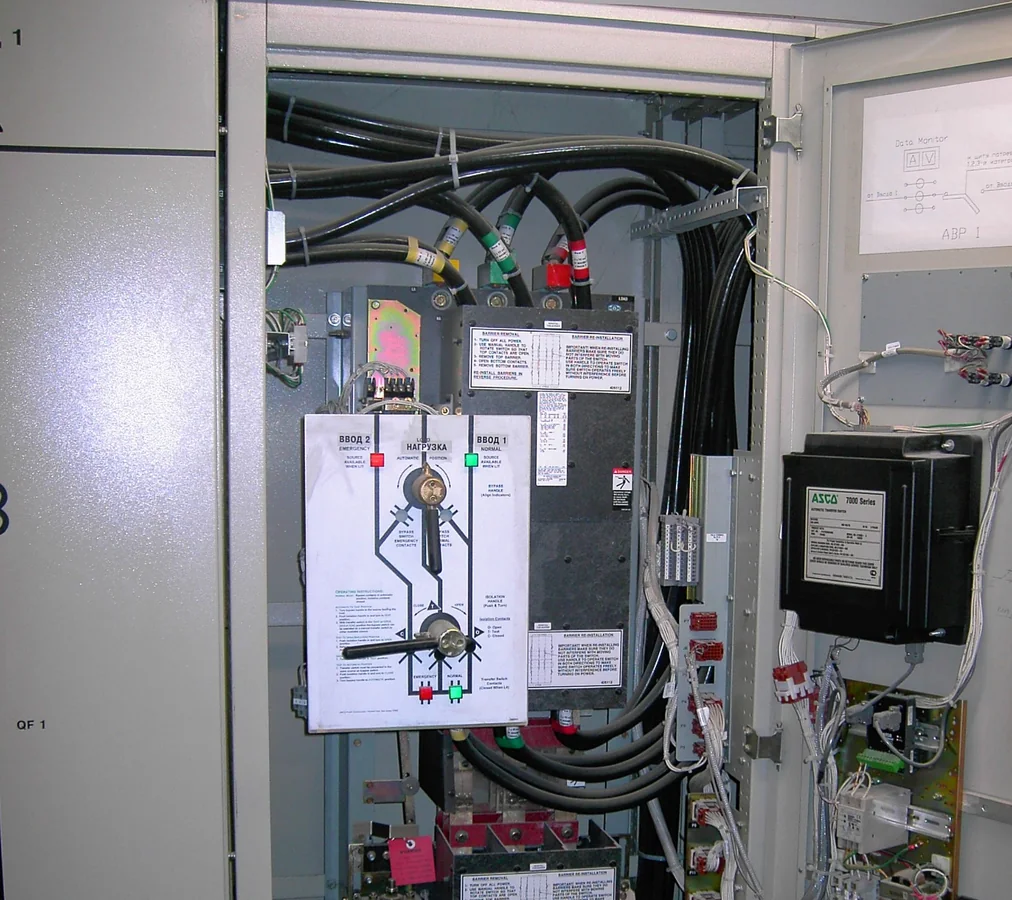
ASCO transfer switch after ATS retrofit
The power circuit needs a verified transfer switch with clearly defined positions, interlocks, service life and manual operation.

Maintenance bypass

Critical loads need a safe way to service the ATS as well as automatic source transfer. A maintenance bypass allows the switching assembly to be taken out of service for repair or testing with less disruption to the facility.

  • Check that the load can be supplied through a path that bypasses the ATS assembly.
  • Provide interlocks to prevent backfeed between sources.
  • Label device positions and indication, and define the sequence for returning to automatic mode.
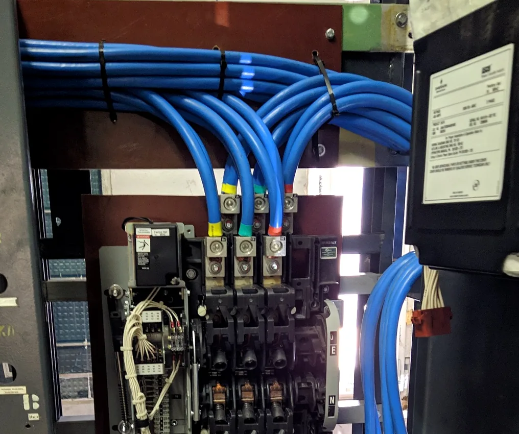
ASCO ATS maintenance bypass in a retrofitted enclosure
A maintenance bypass in an ATS enclosure provides a defined arrangement for supplying the load while the switching assembly is inspected or serviced.

Expanding the system for additional sources

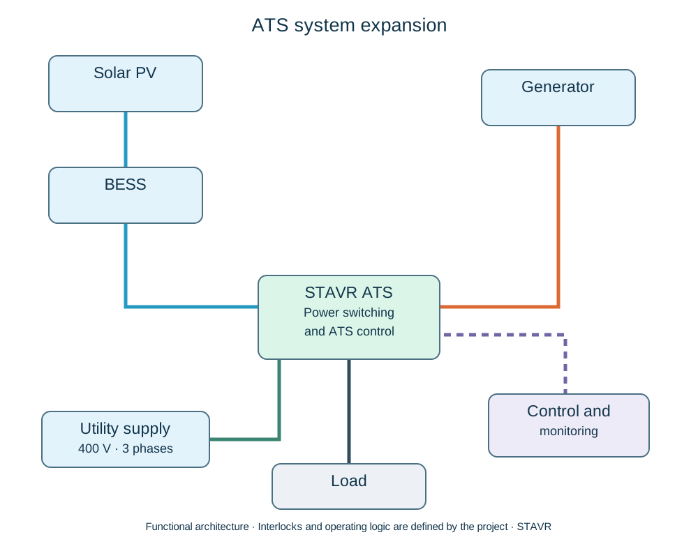
Adding a generator, UPS, BESS, solar PV or second incomer often requires changes to the existing ATS logic. Source priorities, ready signals and a safe return to normal operation must be coordinated.

  • Review the existing single-line diagram.
  • Define source priorities and transfer inhibit conditions.
  • Update control circuits and status signals.
STAVR ATS expansion diagram with BESS, generator, solar PV, monitoring and load
System expansion needs a clear architecture covering the utility supply, BESS, generator, ATS control, monitoring and load, with documented control connections.
Important

A retrofit must not introduce new risks

Practices we avoid

  • Replacing relays without identifying the underlying fault.
  • Leaving undocumented control logic in service.
  • Connecting a new source without checking interlocks.
  • Hiding a system problem behind cosmetic repairs.

Our approach

  • Record the original circuit and the actual condition of the equipment.
  • Identify what to retain, replace and add.
  • Test normal and fault operating scenarios.
  • Provide operating staff with a clear description of the operating sequence.
The practical limit of a retrofit: if the enclosure, busbars, transfer switch or protective devices are unsuitable for the current rating, condition or facility requirements, a new ATS is the better design choice. A retrofit should reduce risk.
FAQ

ATS retrofit: common questions

When is a retrofit preferable to a new enclosure?When the enclosure, selected busbars, cable entries and power switching equipment remain suitable, and the problems concern controls, logic, indication or integration with additional sources.
Can the existing transfer switch be retained?Yes, if it meets the current rating and utilisation category, has functional interlocks and sound contacts, and shows no signs of overheating.
When is a new ATS the better option?When the power switching equipment is worn, current capacity is insufficient, overheating or unsafe connections are present, or adequate interlocking cannot be achieved.
Can a generator, UPS or BESS be added?Yes, after checking source priorities, ready signals, transfer inhibit conditions and the sequence for returning to the preferred source.
Will a maintenance bypass be provided?Yes. The maintenance bypass arrangement and procedure must be documented clearly so that staff understand how to service the ATS safely.
What is needed for an initial assessment?Photos of the enclosure, the nameplate or ATS current rating, the number of incomers, power sources and a brief description of the problem.