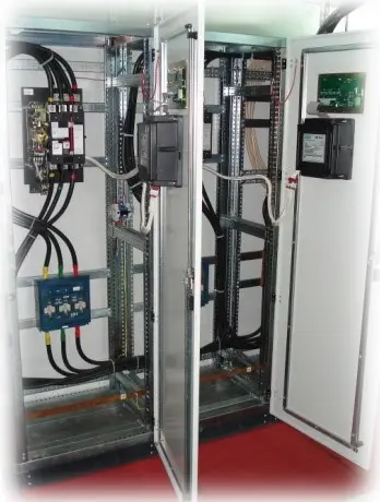
 2×400 A
Two-source ATS
Utility–utility or utility–generator. Source parameter monitoring, mechanical interlocking and a project-specific retransfer sequence.
ATS page
Complete ATS and LV switchboards with ATS based on ASCO Series 7000 automatic transfer switches.
Power switching, control, protection, indication and auxiliary equipment are designed as a complete assembly for the specific power supply arrangement.
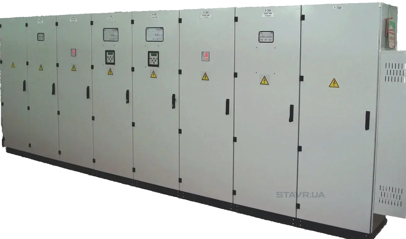
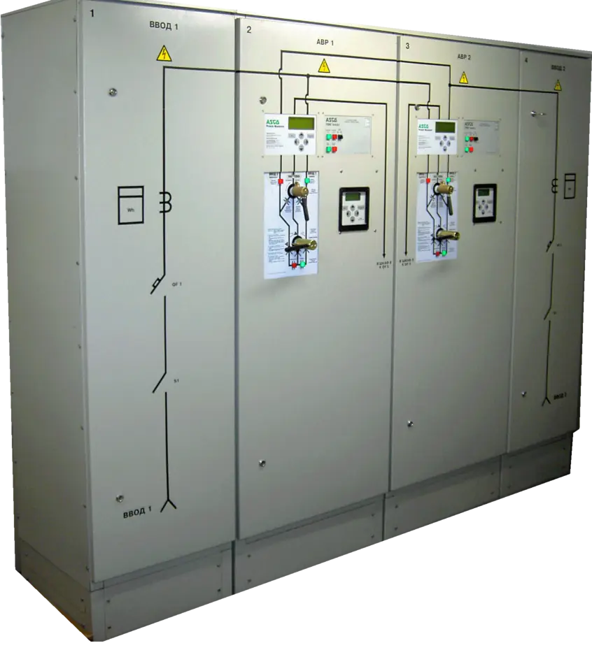
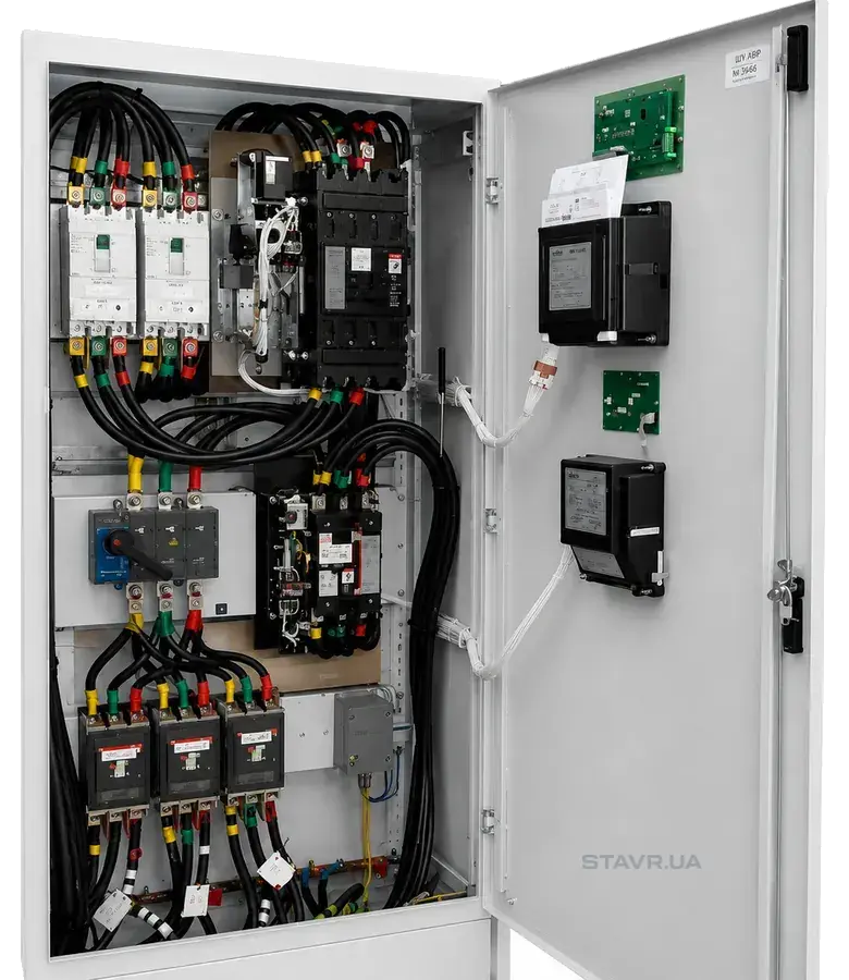
Series 7000 is used in complete ATS assemblies, LV switchboards with ATS, multiple-source systems and no-break transfer configurations. The cabinet equipment is defined by the single-line diagram and the facility’s requirements.
2×400 AUtility–utility or utility–generator. Source parameter monitoring, mechanical interlocking and a project-specific retransfer sequence.
ATS page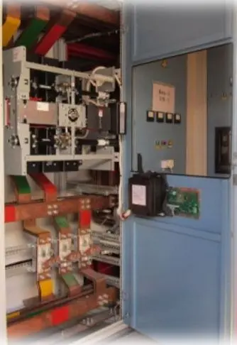 1600 A
A complete high-current ATS: ASCO Series 7000 power transfer switch, busbars, controller, protection, indication and auxiliary circuits in a metal cabinet.
ATS page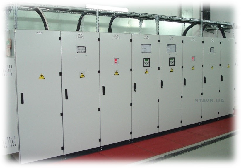 2×800 A
Incoming supply, standby supply, bus sectioning, distribution, protection, metering and control in a coordinated system of metal cabinets.
Complete LV switchboards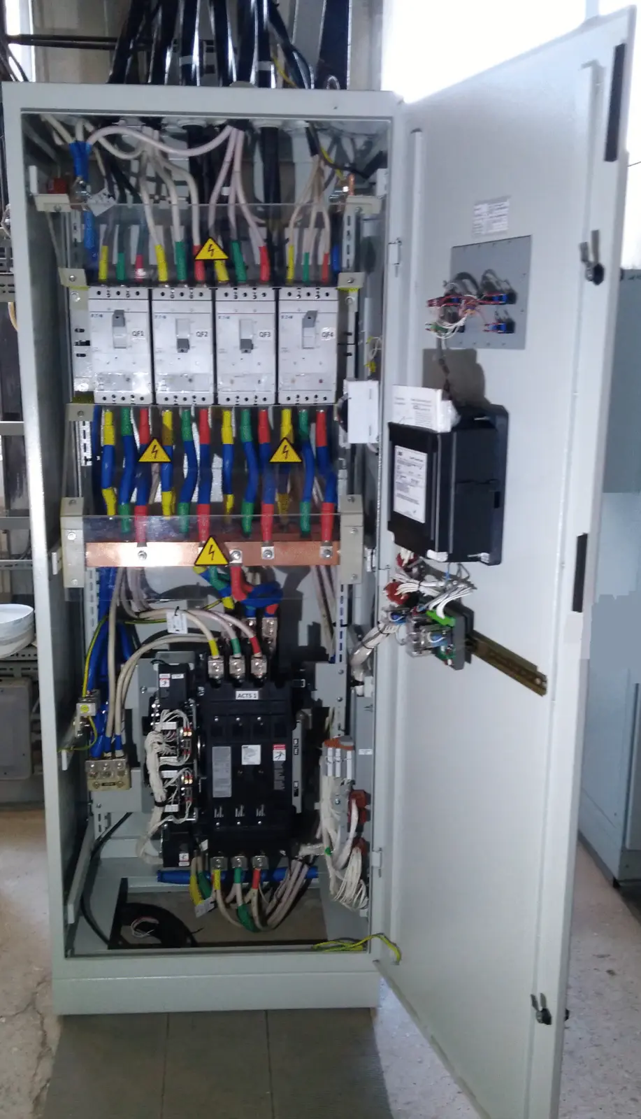 CTTS 800 A
Brief contact overlap is permitted only when the differences in source voltage, frequency and phase angle are within acceptable limits.
No-break transferThe number of sources, power contact positions, neutral switching, permissives and interlocks must be clearly defined in the design documentation.
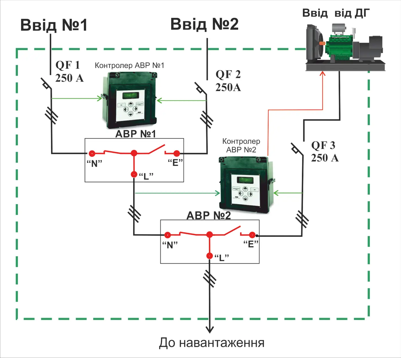
Typical utility–utility–generator architecture: two coordinated ATS units, power switch position monitoring and a generator start/stop command.
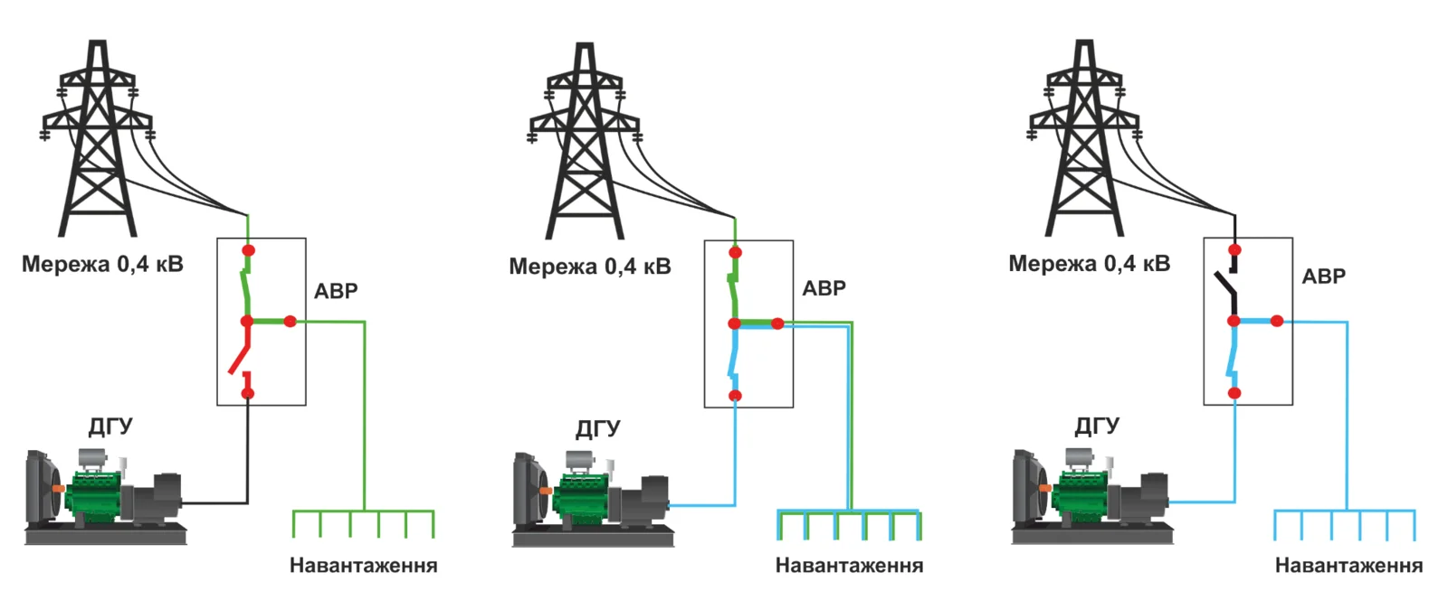
No-break transfer: the controller does not synchronise the sources; it waits until the phase-angle, frequency and voltage differences fall within the set limits. Brief contact overlap is then permitted.
This is the principal difference from STAVR Series WN.
The switch, operating mechanism, power contacts, mechanical interlocks and auxiliary contacts form a single functional assembly. STAVR adds the controller, protection, indication, terminal circuits, metal cabinet and other equipment required by the design.
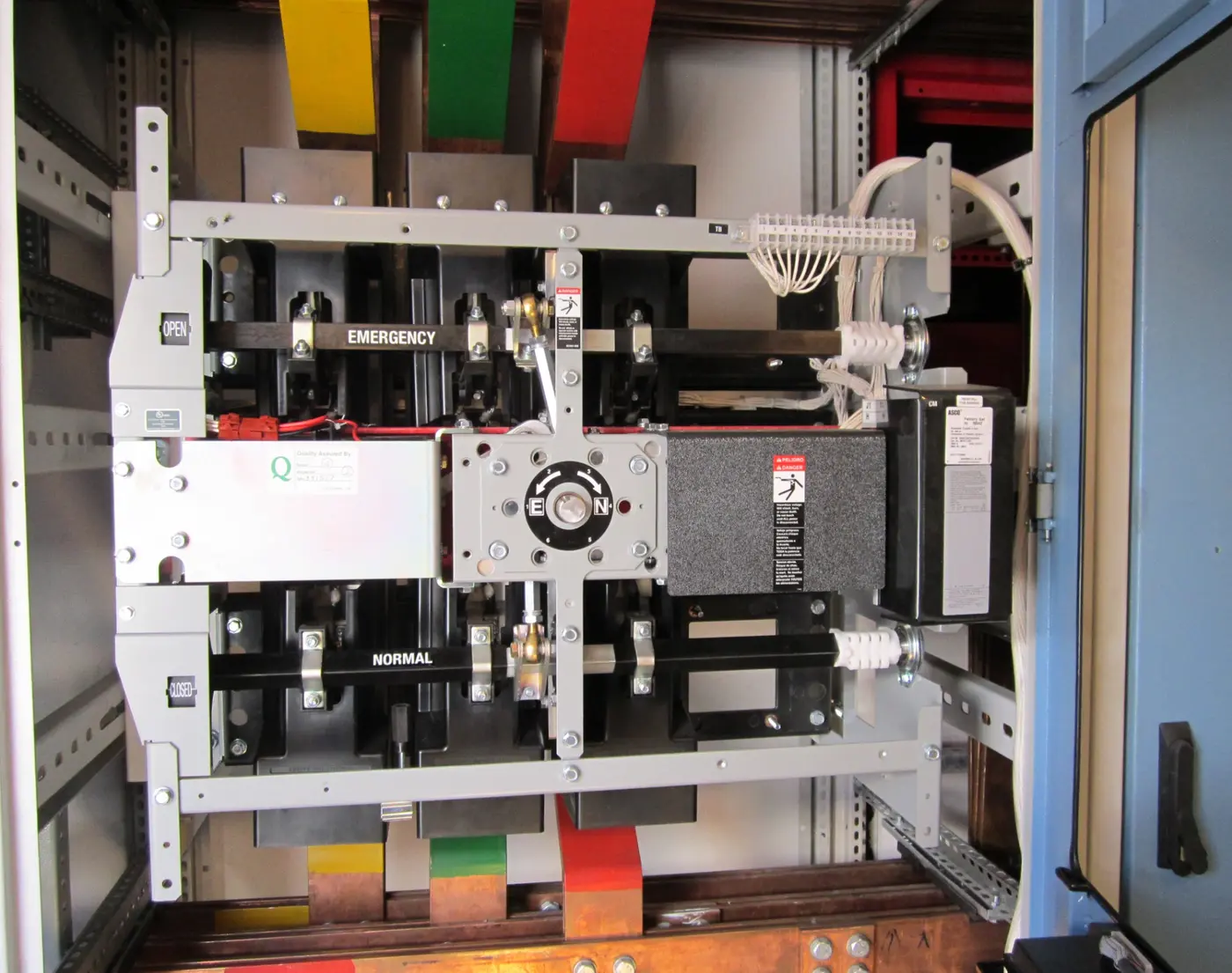 3000 A
An actual 3000 A ASCO Series 7000 power transfer switch installed in a cabinet. The number of poles and operating mechanism configuration are specified for each project.
These photographs show actual equipment assemblies rather than promotional mock-ups. The construction and component arrangement vary with the current rating, circuit and maintenance requirements.
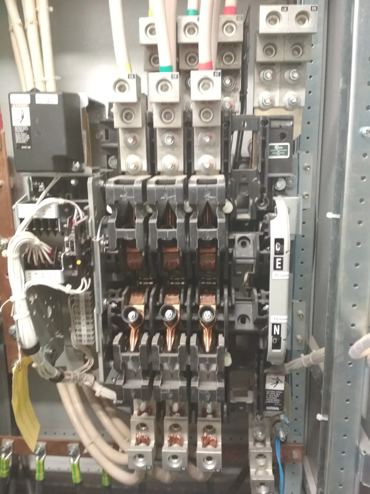
The power contacts, operating mechanism and mechanical linkages are visible. The photograph retains the full working assembly so that construction details remain visible.
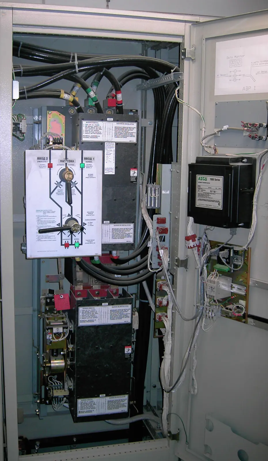
A configuration with bypass and isolation of the power transfer switch for maintenance while supplying a critical load.
3×400 AA three-source LV switchboard with 400 A ASCO Series 7000 devices. The transfer arrangement and source priorities are defined by the technical specification.
The correct operating sequence cannot be selected from the rated current alone. The permissible interruption, motors, UPS, variable frequency drives and process requirements must all be considered.
The previous catalogue covers several ASCO series, so its general figures have not been automatically carried over to the Series 7000 page.
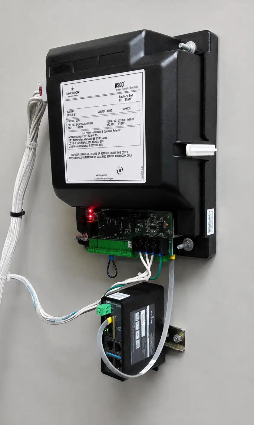
ASCO controller and installed Ethernet / RS‑485 interface module. The available interfaces and protocols are confirmed for the specific equipment configuration.
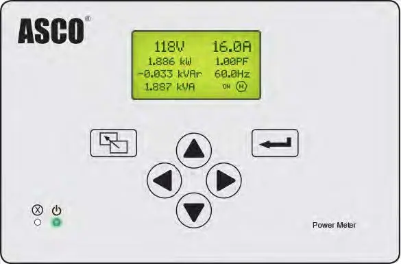
ASCO Power Meter is an optional module for measuring voltage, current, frequency, active, reactive and apparent power, power factor and other electrical parameters.
The controller must support the number of sources, transition method, generator set requirements, measurements, event log and supervisory monitoring. A single model is not assigned to the entire series without defining the equipment configuration.
The switching mechanism is the core of an ATS, but the reliability of the complete system also depends on protection, control, installation, measurement and ease of maintenance.
Four items need to be confirmed for the current Series 7000 specifically: rated current range, current controller models, available communication protocols and the current product designation structure. The page can then be added to the navigation and indexing.
The final ATS configuration is determined by the design current, short-circuit currents, load characteristics, number of sources, neutral arrangement and continuity requirements. See also DSTU EN 60947-6-1 and the article on neutral switching.
Send a single-line diagram or the basic parameters: current, voltage, sources, number of incoming supplies and poles, transition type, bypass, protection and supervisory monitoring requirements.