Solutions for facilities that need to manage three power sources: Utility 1 / Utility 2 / Generator, Utility / Generator 1 / Generator 2, Two bus sections + Generator, or similar backup arrangements. STAVR delivers a complete system with priorities, interlocks and operating logic tailored to the facility.
An ATS may have three different power sources. Backfeed — for example, a generator feeding power into the utility network — can damage equipment and endanger personnel.
STAVR ATS systems therefore incorporate mechanical and electrical interlocks that prevent a generator from being connected to multiple incoming supplies simultaneously.
A three-source ATS is used where a standard utility/generator arrangement is no longer sufficient: source priorities, interlocks, status indication and monitoring of each source are required.
Solution overview
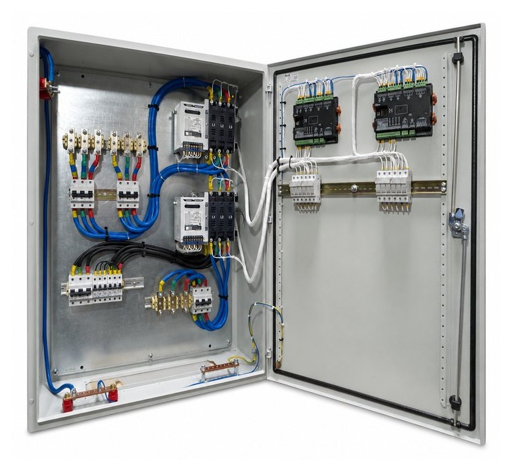
A STAVR three-source ATS is an intelligent system for automatically transferring the load between three power sources. It safely disconnects the load from one source and connects it to another according to the specified priorities, source conditions and facility requirements.
STAVR designs the three-source ATS as a complete assembly: power switching, controls, interlocks, indication and priority logic work together as one system tailored to the facility.
The design incorporates mechanical and electrical interlocks to prevent backfeed or simultaneous connection of sources to the load. Position indication can show Source 1, Source 2, Source 3 and, depending on the selected arrangement, a disconnected or maintenance position.
Each source has its own monitored parameters and conditions for connection. During transfers, the system blocks incorrect operating states and manages safe connection, disconnection and restoration of the sources.
Three-source ATS features
The ATS configuration is selected for the specific power scheme, load current, transfer requirements and site operating conditions.
rated voltage: 230 V or 400 V AC, 50 Hz;
rated current: 100 A to 3000 A;
three or four poles, with neutral switching where required;
compliance with DSTU EN 60947-6-1:2018 / IEC 60947-6-1 and, where required, UL 1008;
mechanical and electrical interlocks against unintended interconnection of power sources;
delayed-transition, fast open-transition or closed-transition configurations, according to the project specification;
a solenoid drive mechanism with high endurance and field-proven reliability;
self-cleaning main contacts;
arc grids, enclosed arc chutes and an increased contact air gap;
segmented silver-tungsten alloy contacts and separate arcing contacts;
local and remote monitoring, signalling and control capabilities.
ATS controller
Control of three power sources
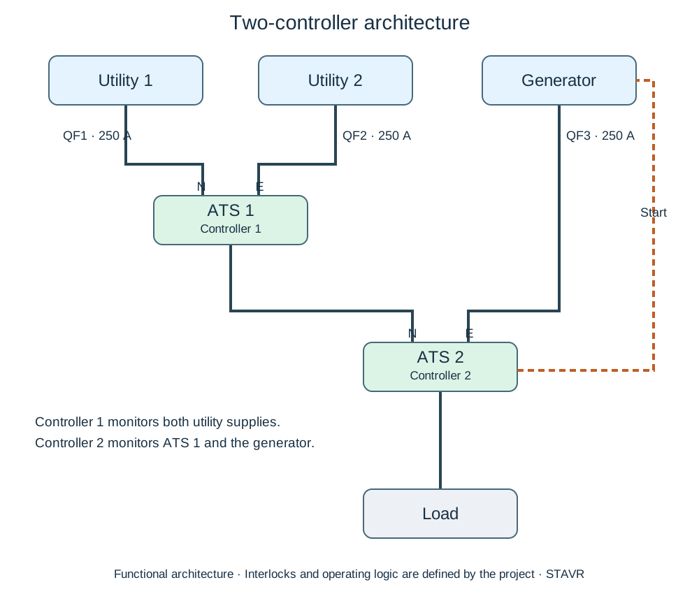
The three-source ATS uses two controllers operating as a single control system. In addition to transferring the load, they manage source priorities, monitor power quality at each incomer and prevent incorrect operating states.
the first controller monitors and controls transfer between the two utility incomers;
the second controller detects loss of both utility supplies and manages connection of the third, backup source — a generator or BESS;
voltage availability and quality are monitored at all three incomers;
power source priorities are configurable;
event logging, alarms and remote monitoring are provided.
This solution is used at facilities with demanding continuity requirements, where several independent sources are available or backup operation requires defined priorities.
two utility incomers and a generator;
utility, generator and UPS / BESS;
two generators and the normal utility supply;
complex LV distribution boards, main switchboards or existing panel retrofits.
More than an additional incomer
A three-source arrangement requires both suitable power switching equipment and correct priority logic: which source is normal, which is backup, when retransfer is permitted and when the load must be disconnected.
Incorrect logic can create more problems than the absence of a third incomer.
Electrical and mechanical interlocking
Backfeed is hazardous in a three-source system: for example, generator power feeding into the utility network, or two incomers being connected together unintentionally.
STAVR ATS systems use mechanical and electrical interlocks to prevent incorrect interconnection of sources and protect equipment and personnel.
Power switching equipment
The configuration is selected for the current, voltage, number of poles, utilisation category, short-circuit conditions and maintenance access requirements.
Manual and maintenance modes
Critical facilities require manual control, position indication, interlocks against incorrect operation and provision for safe maintenance.
Monitoring and signals
Where required, the ATS transmits status signals to supervisory monitoring, SCADA or BMS systems. Dry contacts, Modbus and other interfaces are available.
Typical power arrangements
Three incomers require more than an extra circuit breaker. The key decisions are source priorities, when generator start is permitted, when to return to utility power and which operations must be interlocked. The following are typical STAVR ATS architectures.
An arrangement for facilities with two independent utility incomers and a diesel generator.
An arrangement for facilities with a standby or redundant diesel generator.
An arrangement for facilities where backup power is supplemented by energy storage or UPS.
An arrangement for facilities with separate load sections and individual supply priorities.
Power arrangement
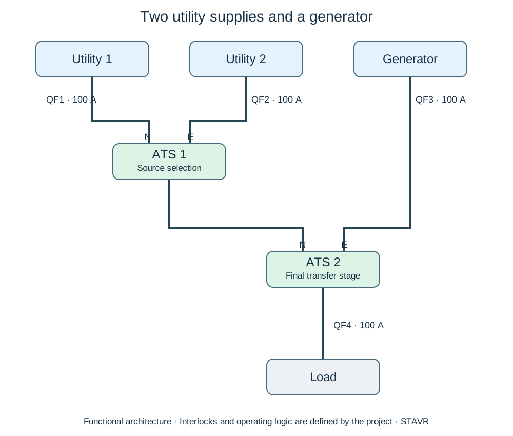
Two utility incomers + Generator. A typical arrangement for facilities with two independent incomers and a standby diesel generator.
The diagram shows the power sources and cascaded transfer stages. Priority and interlocking logic are defined for the facility. This diagram explains the architecture. The complete component list, device labels, interlocks and operating sequence are defined by the project design.
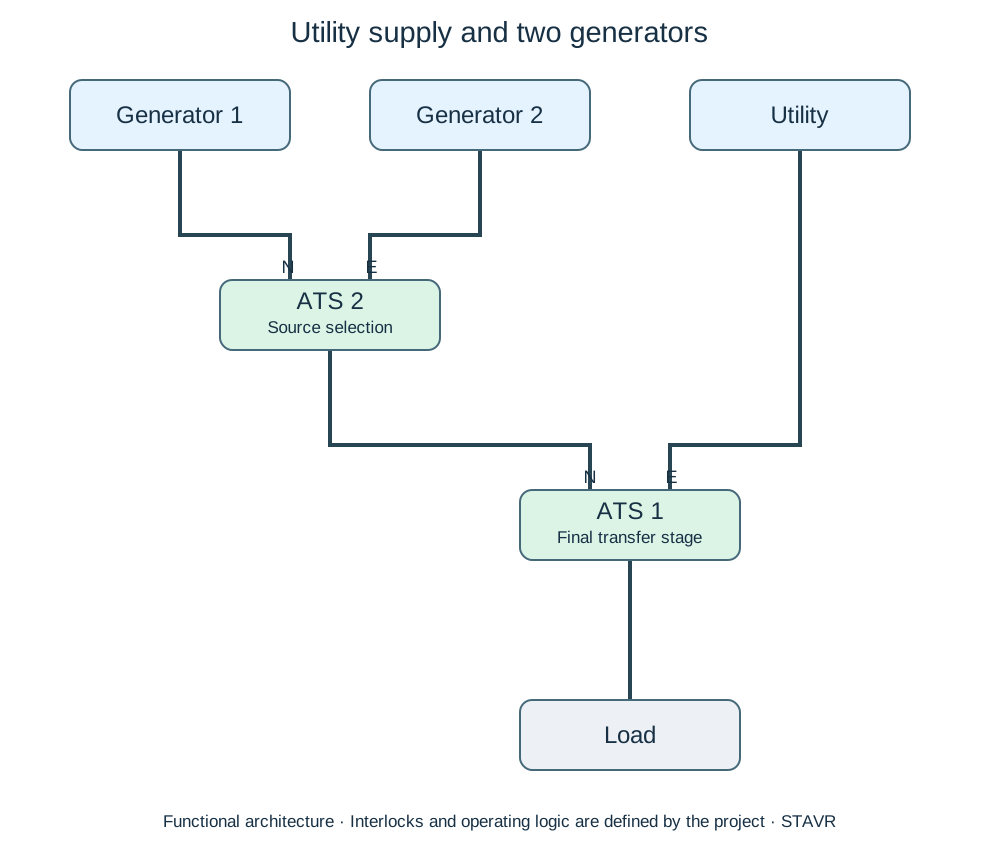
Utility + Generator 1 + Generator 2. A typical arrangement for facilities with a standby or redundant backup generator.
The diagram shows the utility supply and two generators. Starting and transfer priorities are defined by the project specification. This diagram explains the architecture. The complete component list, device labels, interlocks and operating sequence are defined by the project design.
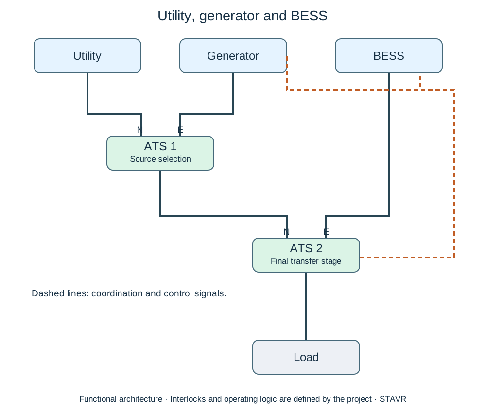
Utility + Generator + BESS. A typical arrangement for facilities where backup power is supplemented by energy storage or UPS.
The diagram shows coordination between the utility, generator and BESS. Charging, backup operation and source priorities are defined for the facility. This diagram explains the architecture. The complete component list, device labels, interlocks and operating sequence are defined by the project design.
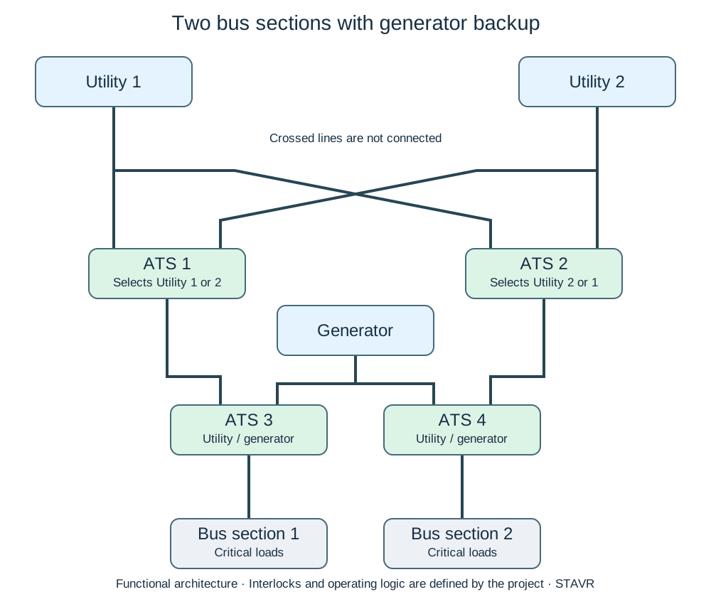
Two utility incomers + Generator + Two bus sections. A typical arrangement for facilities with separate load sections and individual supply priorities.
The diagram shows backup supply for two load sections. Priorities, interlocks and bus-section operating modes are defined by the project specification. This diagram explains the architecture. The complete component list, device labels, interlocks and operating sequence are defined by the project design.
Source priorities, interlocks, retransfer to the normal source and manual operation are defined by the project specification, site operating modes and load characteristics.
Initial information for selection
To select a three-source ATS, provide the number and type of power sources, voltage, load current, number of poles, required source priorities, generator operating mode, and requirements for manual control, signalling and supervisory monitoring.
Click to open the form ↓
Initial project requirements
Send your three-source ATS requirements
Enter the main parameters of the power arrangement. You can attach a photo or specification if available.