01
Fast in-phase transfer
Fast transfer takes place only under in-phase conditions. The controller checks the voltage, frequency and phase-angle differences between the sources and determines when a command to the operating mechanism is permitted.

The controller monitors the power sources, implements the transfer sequence, controls generators, records events and sends data to the supervisory system.
The specific controller model is defined by the technical specification. The functions depend on the ATS circuit, number of sources, power switch type and monitoring requirements.
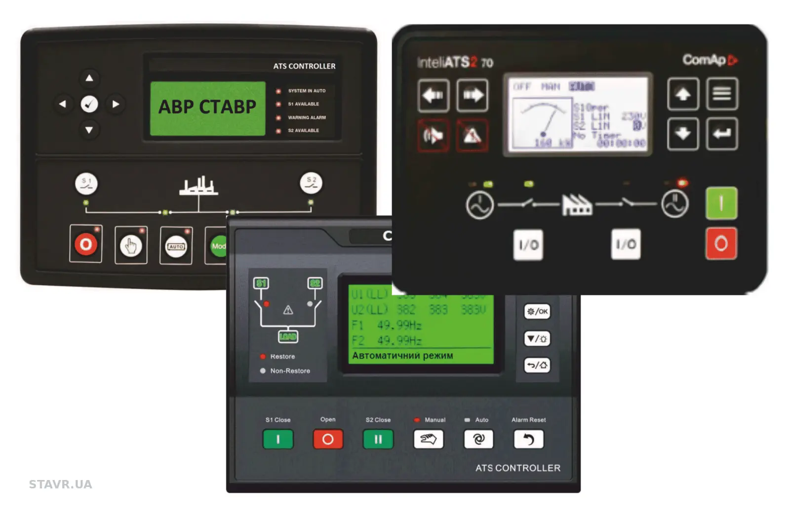
The controller does more than command the operating mechanism. It checks permissives, power switch position, priorities and interlocks.
Fast transfer takes place only under in-phase conditions. The controller checks the voltage, frequency and phase-angle differences between the sources and determines when a command to the operating mechanism is permitted.
The controller checks the phase sequence of the normal and standby sources and inhibits transfer if the phase rotation is incorrect.
Upper and lower voltage thresholds are set separately for the normal and standby sources. Values outside the set limits are taken into account by the transfer logic.
Automatic transfer with selection of a preferred source and configurable retransfer after that source recovers.
Equal-priority source operation without automatic retransfer when the previous source recovers.
The controller prevents the load from being supplied by a source whose parameters are outside the set limits and performs transfer or disconnection according to the configured sequence.
Overload monitoring with provision for disconnecting non-priority circuits or the entire load according to the configured operating sequence and ATS equipment.
Forced source selection or movement of the power transfer switch to the open centre position.
A password protects operating parameters from unauthorised or accidental changes.
Configurable delays for responding to source failure, transferring to the standby supply and retransferring after the normal supply recovers. The delays prevent transfer in response to brief voltage dips.
Parameters are displayed per phase and used both for ATS logic and operational monitoring.
Measurement of total harmonic distortion of voltage (THD U) and current (THD I), and display of individual harmonics from the 3rd to the 21st order, with the appropriate controller configuration.
Per-phase voltage monitoring at the output of the complete ATS assembly.
Per-phase measurement through current transformers.
Active power P, reactive power Q, apparent power S and power factor cos φ.
After a fault, the sequence of states and the parameters preceding transfer provide the evidence needed for analysis.
The real-time clock records the date, time, operating mode changes, fault conditions and transfer commands.
The controller can store five data sets for transfer events for detailed analysis.
The start sequence is coordinated with the ATS circuit, generator readiness, time delays and load retransfer conditions.
Start and stop control of one or two generators according to the selected circuit arrangement. Two-generator systems can implement duty rotation or a prime/standby arrangement.
Daily, weekly or monthly generator test runs.
Scheduled on-load or off-load generator runs, where provided for in the design.
The interfaces provide access to parameters, measurements and the event log without intervention in the ATS power switching section.
On-site commissioning, parameter changes and software updates.
Galvanically isolated port for communication using Modbus RTU.
Remote data exchange using Modbus TCP/IP and integration with the supervisory system.
Output contacts can operate in pulsed or maintained mode.
The total time includes controller response and mechanical operation of the power transfer switch. The actual value depends on the rated current, construction and mass of the moving parts: high-current devices take longer to transfer.
0 ms is not the mechanism operating time. It can only describe the absence of a supply interruption during no-break transfer with synchronised sources and brief contact overlap.
Controller selection requires the source arrangement, power switch type, rated current, generator operating sequence, signal list and supervisory monitoring requirements.