01
In-Phase Monitor — Feature 27
This function is available on the relevant 7ATS/7ATB configurations with Feature 27 (In-Phase Monitor) and delays the command until the relative phase angle between the sources is acceptable.

In STAVR Series 7000 ATS, the ASCO Group 5 controller monitors the power sources and controls the power transfer switch. The optional Power Meter adds electrical measurements.
The Group 5 controller, optional Power Meter and optional 72EE2 / ASCO 5170 QEM module form the control and monitoring system. The specific functions are determined by the ATS configuration and technical specification.
More about ASCO-based STAVR Series 7000 ATS and LV switchboards.
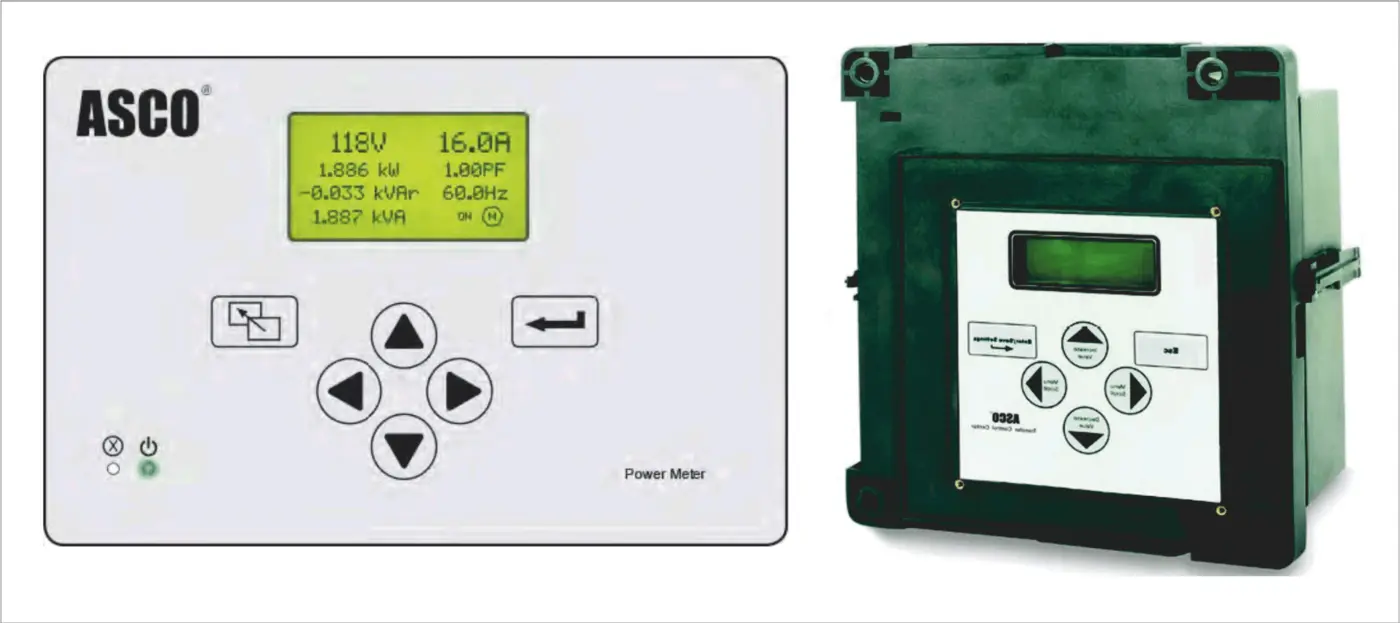
The controller does more than command the operating mechanism. It checks permissives, power switch position, priorities and interlocks.
This function is available on the relevant 7ATS/7ATB configurations with Feature 27 (In-Phase Monitor) and delays the command until the relative phase angle between the sources is acceptable.
Three-phase monitoring checks the phase sequence of the normal and standby sources; the reference sequence is defined in the settings.
Upper and lower voltage thresholds are set separately for the normal and standby sources. Values outside the set limits are taken into account by the transfer logic.
Automatic transfer with selection of a preferred source and configurable retransfer after that source recovers.
Equal-priority source operation without automatic retransfer when the previous source recovers.
The controller evaluates source voltage, frequency and phase conditions and permits transfer only when the set conditions are met.
Overload monitoring with provision for disconnecting non-priority circuits or the entire load according to the configured operating sequence and ATS equipment.
Forced source selection or movement of the power transfer switch to the open centre position.
A password protects operating parameters from unauthorised or accidental changes.
Configurable delays for responding to source failure, transferring to the standby supply and retransferring after the normal supply recovers. The delays prevent transfer in response to brief voltage dips.
The controller uses source parameters for ATS logic, while the optional ASCO Power Meter extends supply and load measurements for operation and monitoring.
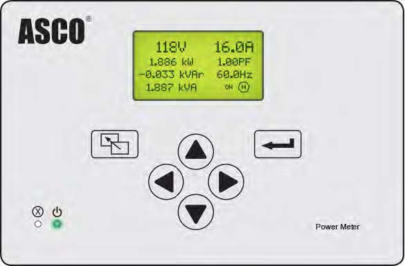
The ASCO Power Meter measures electrical quantities and makes them available on the local display and through a serial interface. THD is measured by the Power Meter, not by the ATS controller.
Phase-to-neutral and phase-to-phase voltages, and their average values.
Current in each phase, neutral conductor current and average current.
Active power in kW, reactive power in kVAR and apparent power in kVA, per phase and total; power factor PF.
Imported, exported and net energy in kWh; leading, lagging and total reactive energy in kVARh; total apparent energy in kVAh.
Supply frequency, total harmonic distortion of voltage (THD U) and current (THD I). These parameters are measured by the optional Power Meter, not by the ATS controller.
Maximum power demand in kW for hourly, daily, monthly, annual and other periods, referenced to the real-time clock.
After a fault, the sequence of states and the parameters preceding transfer provide the evidence needed for analysis.
The real-time clock records the date, time, operating mode changes, fault conditions and transfer commands.
The controller displays the current source and power switch status, active warnings and the reasons for operating mode changes.
The start sequence is coordinated with the ATS circuit, generator readiness, time delays and load retransfer conditions.
The controller issues the emergency generator start command and manages the retransfer sequence after the normal source recovers.
The start time, day of the week, week of the month and running duration are set for each programme.
A test run can transfer the load to the emergency source or run the generator without transferring the load.
Optional 72EE2 / ASCO 5170 QEM module: Ethernet, RS-485, Modbus TCP/IP or RTU and SNMP, depending on the configuration. The ASCO Group 5 controller and optional Power Meter connect to the 72EE2 / ASCO 5170 QEM module, which forwards the data to the supervisory system.
Sends source status, switch position, commands and alarm messages to the 72EE2 / ASCO 5170 QEM.
Sends measured electrical quantities for the supply and load to the 72EE2 / ASCO 5170 QEM.
Combines controller and Power Meter data and prepares it for transmission to an external system.
The 72EE2 / ASCO 5170 QEM transmits data using the selected interface and protocol, depending on the configuration.
The actual transfer time is determined by the power switch mechanism configuration.
0 ms means no interruption to the power supply, not zero mechanism operating time. In CTTS, brief parallel overlap is permitted only after the source synchronism conditions have been met.
Controller selection requires the source arrangement, power switch type, rated current, generator operating sequence, signal list and supervisory monitoring requirements.