
This article examines the differences between N, N+1 and 2N, their relationship to Tier levels, the role of ATS units in data centre arrangements, and STAVR LV switchboard solutions with ATS for normal, fault and maintenance conditions.
Need to review your redundancy architecture? Send a single-line diagram: STAVR engineers will assess the sources, shared components, maintenance modes and the power path to the load.
Send a diagramLoad capacity and power-source transfer
Will sufficient capacity remain after a power source fails? The equipment remaining in operation must support the load after it is redistributed.
Will transfer to the standby source remain available? A healthy source of sufficient capacity must be connected to the load through operational switching devices, busbars and cables. Redundancy is assessed along the entire circuit, up to the final load inputs.
N: the required capacity without redundant equipment
The designation N means the number of equipment units or the capacity required to supply the design load.
For example, if operation requires two identical UPS modules and exactly two are installed, there is no redundant module. Losing one may leave insufficient capacity.
The data centre may nevertheless have both utility power and a generator. Having an alternative power source does not mean that every item of equipment in the system is redundant.
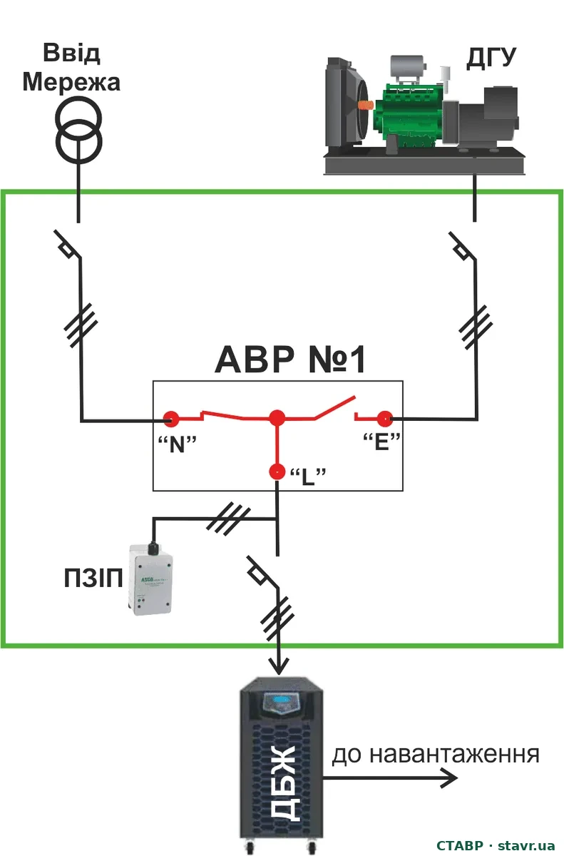
N+1: one additional capacity component
In an N+1 configuration, one redundant component is added to the capacity required for operation. This may be a generator set, a UPS module or another component that maintains the design capacity after a single failure. The designation “+1” does not necessarily mean one separate physical unit.
Calculations use the capacity available under actual operating conditions. For unequal modules, the loss of the largest module and all intended operating modes must be checked.
N+1 generator or UPS capacity does not mean N+1 for the entire system. Shared ATS units, busbars, bypasses and switchboards require separate assessment.
Comparison of redundancy principles
| Configuration | What is made redundant | What must be checked |
|---|---|---|
| N | Only the required capacity; no redundant equipment | Consequences of losing one system element |
| N+1 | Capacity: one additional component | Sufficient capacity after a failure; shared transfer and distribution components |
| 2N | Two independent paths, each rated for 100% of the critical load | Independence of the entire circuit and separate A/B inputs to the load |
Example: a 600 kW critical load
- Two 300 kW UPS modules form an N configuration. Both modules are required for operation.
- Three 300 kW modules, two of which supply the load, form an N+1 configuration. After one is lost, 600 kW remains.
- Two independent paths, A and B, each rated at 600 kW, form a 2N configuration. Each path can carry the entire critical load.
Additional note. If each path has its own redundant module, the configuration can be designated 2(N+1).
This is a simplified example: it does not account for power factor, overload capability, harmonics, battery charging, inrush currents or the characteristics of specific equipment. It explains the principle rather than selecting equipment ratings.
Additional generating capacity does not remove dependence on a shared distribution component. Counting modules must therefore always be supplemented by an assessment of switching, protection and maintenance.
2N: two independent paths, each rated for 100% of the critical load
Each path, A and B, must support 100% of the design critical load. Independence is maintained along the entire corresponding power circuit, from the power sources to the separate inputs of the IT equipment.
In server equipment with two power supplies, one is connected to A and the other to B. Each power supply and path must support the required operation after the other input is lost. Single-input loads require a separate solution consistent with the permissible interruption.
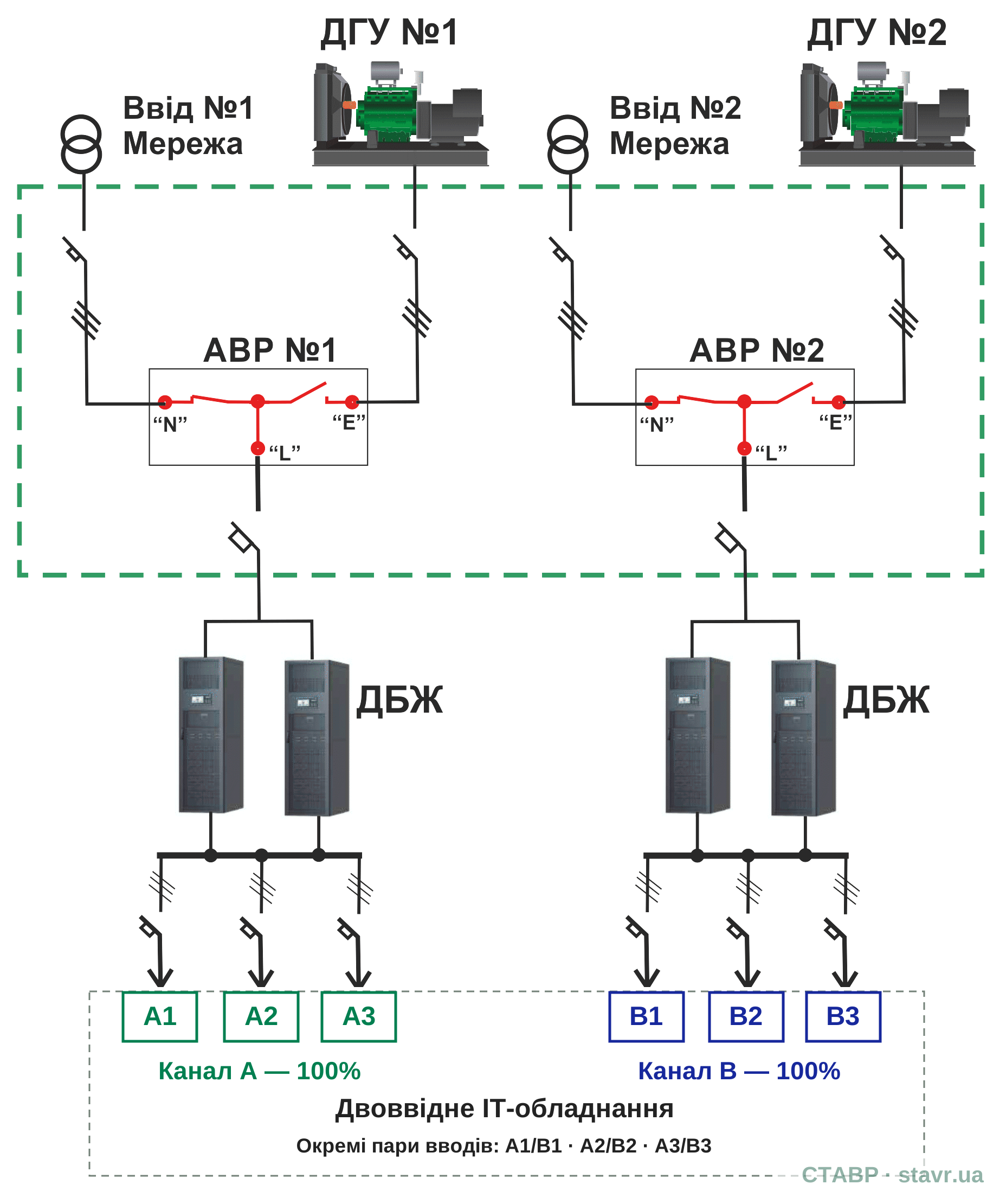
A shared non-redundant component can limit the capabilities of a 2N architecture. Shared control systems, maintenance modes and the effect of a failure in one path on the other must also be checked.
Two paths for separate load groups
Two utility supplies, two generator sets and two UPS groups can supply separate IT load groups. This differs from connecting the same critical load to two independent paths according to the 2N principle.
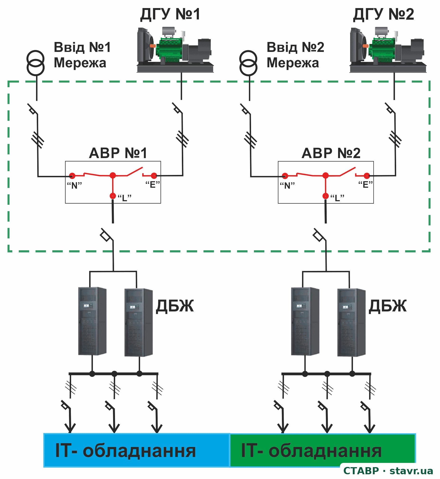
In each path, the ATS transfers between its own utility supply and generator set. The UPS group's redundancy level is determined by the number and capacity of units required for the corresponding load.
Dedicated and distributed redundancy
Large data centres can use redundant capacity in different ways.
Dedicated redundancy. A separate standby system can replace one of the operating systems. For example, two systems supply their own load groups, while a third is intended to take over the load of either one. This requires sufficient capacity and suitable transfer circuits and devices.
Distributed redundancy. The load is shared among several systems, each with spare capacity for operation after another fails. If three systems each carry approximately one third of the total load, taking one out of service means the other two must each carry approximately one half.
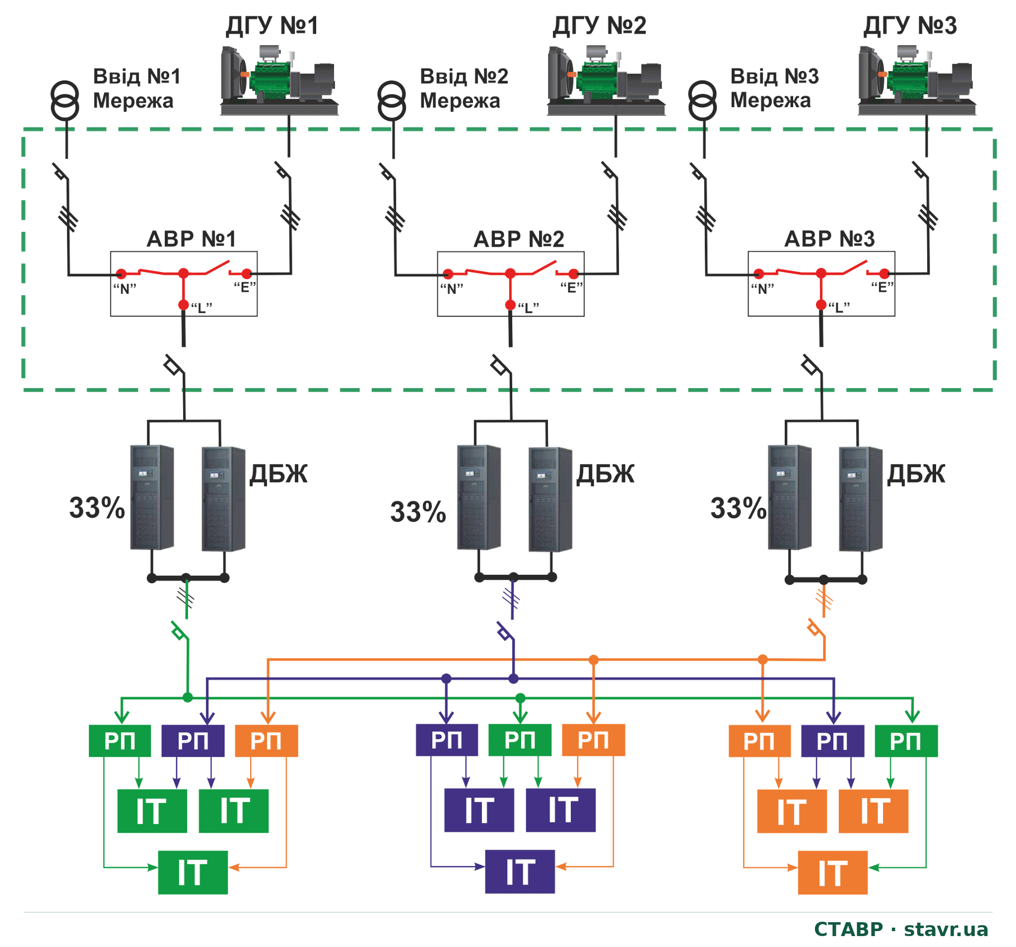
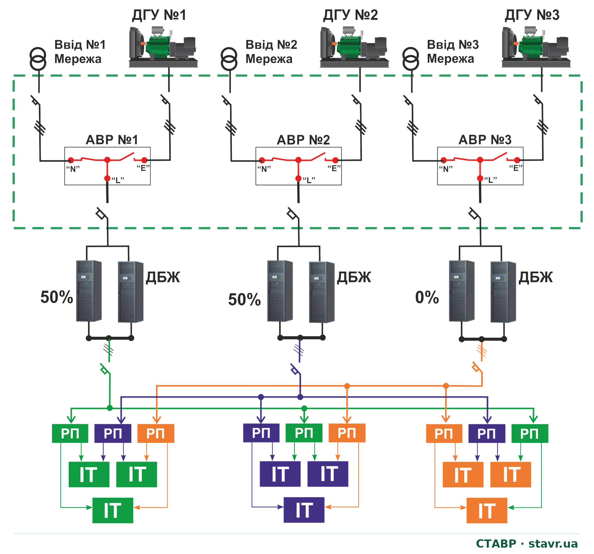
These shares refer to the total data centre load. The capacity of each system is determined by the highest load it must support in the intended operating modes. The diagrams illustrate distributed redundancy; Tier compliance is assessed for the data centre's entire infrastructure, rather than from an individual illustration or component.
How redundancy relates to Tier levels
The Uptime Institute classification describes the characteristics of data centre infrastructure, including power and cooling. It evaluates the performance of the architecture, rather than simply the amount of redundant equipment.
| Level and official designation | Main characteristic |
|---|---|
| Tier I — Basic Capacity | Basic capacity; maintenance may require the load to be shut down. |
| Tier II — Redundant Capacity Components | Redundant capacity components; shared distribution paths may remain a limitation. |
| Tier III — Concurrently Maintainable | Planned removal of equipment and distribution paths for maintenance without shutting down the critical load. |
| Tier IV — Fault Tolerant | Fault tolerance in addition to concurrent maintainability. |
N+1 does not automatically demonstrate Tier III compliance, nor does 2N demonstrate Tier IV. A STAVR LV switchboard with ATS can nevertheless be designed as a critical power-system component in accordance with the project requirements for the target Tier architecture.
STAVR LV switchboards with ATS in data centre redundancy architectures
A STAVR LV switchboard with ATS is a critical component of the data centre power system. Its circuit arrangement, equipment, interlocks, maintenance modes and monitoring facilities can be designed in accordance with the project requirements for the target Tier level.
Depending on the data centre architecture, STAVR solutions can incorporate independent power paths, maintenance bypass, Dual ATS, in-phase transfer, closed transition and a redundant power supply for the monitoring system. These functions provide the design-specified redundancy, maintainability and fault tolerance for the corresponding part of the system.
A Tier level is determined for the data centre's infrastructure as a whole. Correct configuration of the STAVR LV switchboard with ATS is an essential part of implementing the target architecture; the final result also depends on power sources, UPS systems, distribution paths, cooling, controls and other facility equipment.
Source of definitions: Uptime Institute — Tier Classification System.
Why ATS reliability has particular requirements
The arrangements discussed show how to retain sufficient capacity after an equipment failure. The next question is whether the system can connect that capacity to the load. In many arrangements, this depends on a single ATS.
In data centre power systems, utility supplies, generator sets, UPS modules and other capacity components are made redundant according to the selected architecture. After one component fails, the equipment remaining in service must supply the load.
However, many arrangements use one ATS to transfer between the normal and standby power sources. Adding a second generator or a redundant UPS module does not itself duplicate this switching device.
If the ATS fails to perform the required operation, a healthy standby source may remain unavailable to the load. A single ATS becomes a shared critical component and, within the corresponding circuit, a potential single point of failure.
Data centre ATS units therefore have more demanding requirements for:
- reliability of the power switching mechanism and mechanical and electrical interlocks;
- monitoring the actual positions of switching devices and confirming command execution;
- fault-current withstand capability and coordination with protection;
- monitoring power-source parameters and control-system operation;
- self-diagnostics and event logging, in configurations that provide these functions.
High ATS reliability reduces the probability of failure but does not replace architectural redundancy or maintainability. Where the project requires the ATS to be taken out of service without a prolonged interruption to the critical load, an external maintenance bypass or a Dual ATS arrangement is used.
In a 2N architecture, the second path can compensate for the unavailability of the first. In an arrangement with a shared transfer component, that component's operation directly determines whether transfer to standby is possible.
Three power sources: two cascaded ATS units
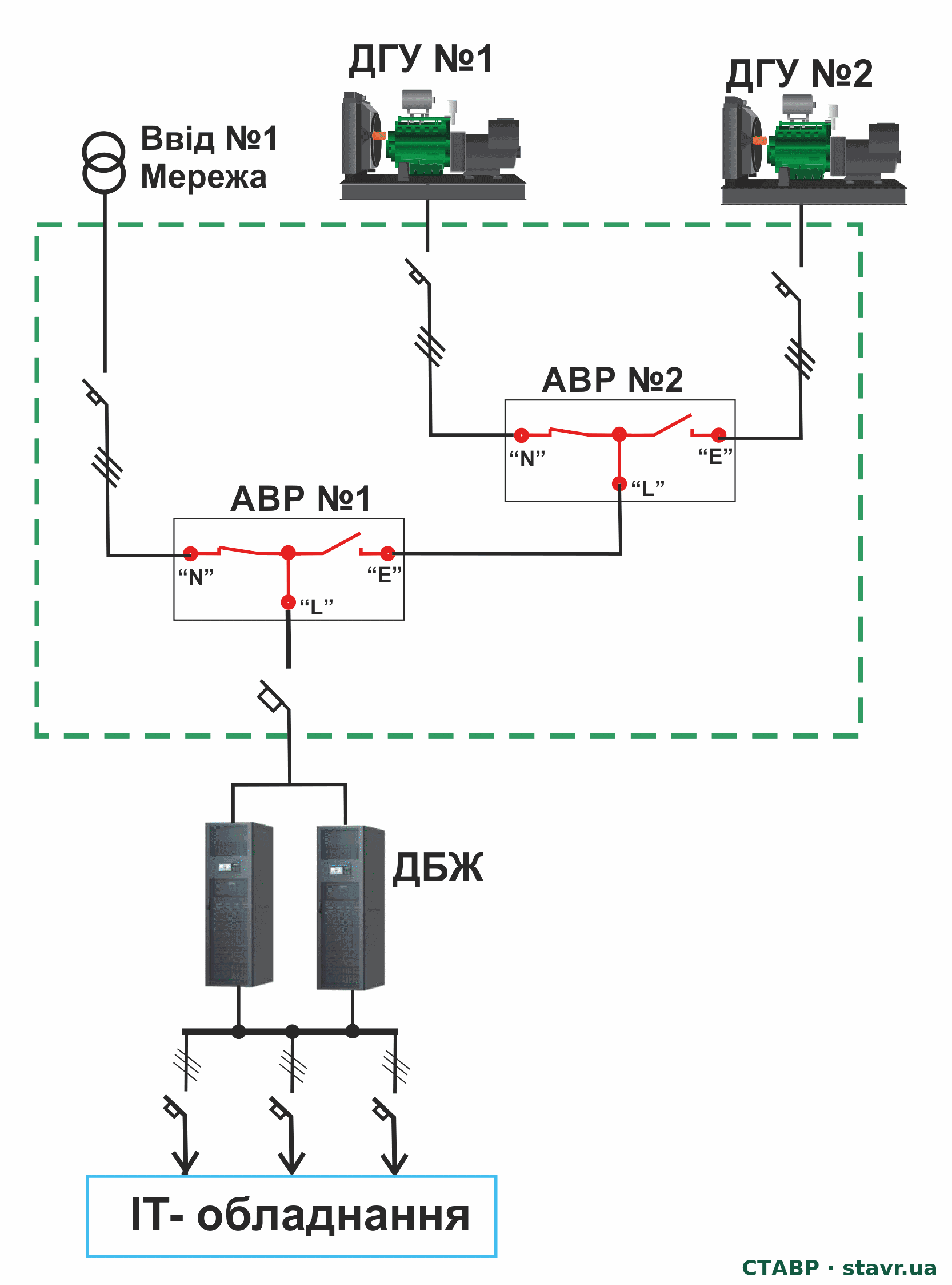
The single-line diagram shows two utility supplies and a standby generator source. ATS No. 1 selects one of the utility supplies, while ATS No. 2 selects the output of ATS No. 1 or the generator set.
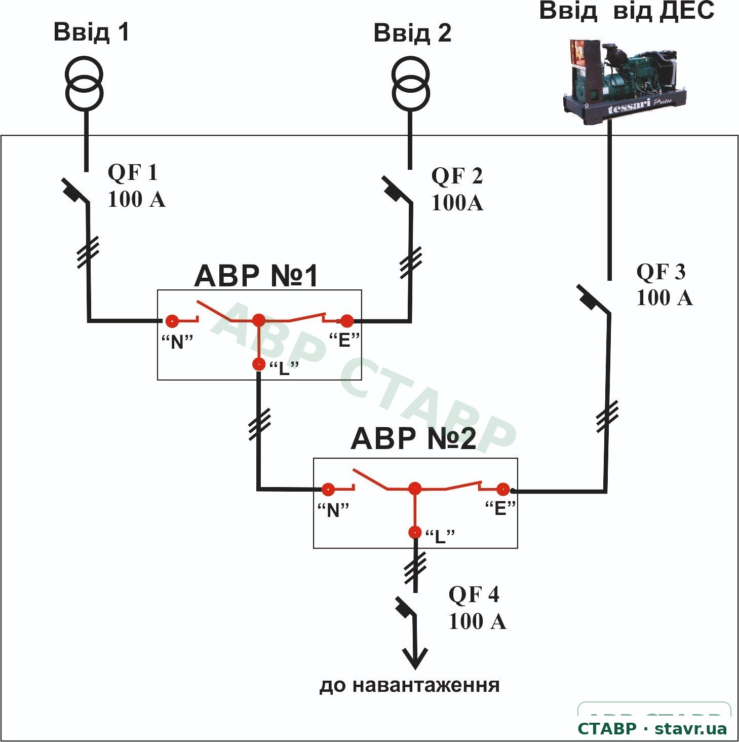
The cascade selects among three power sources but does not duplicate the function of either ATS. Source capacities, device ratings, priorities and interlocks are determined for the specific load. The UPS and downstream power distribution are not shown in this diagram.
Data centre power redundancy with STAVR LV switchboards with ATS
STAVR LV switchboard solutions with ATS are intended for loads distributed across two or three sections. Source transfer in these solutions uses dedicated ATS devices without bus-section circuit breakers.
This allows the arrangement to follow the data centre's load structure, defining the section power sources, their priorities and the sequence for transfer to standby. The specific configuration is selected according to the required capacity and permissible operating modes.
An LV switchboard with ATS combines incoming supply, distribution, protection and power transfer in one complete electrical assembly. The power section, controller, interlocks, indication and documentation are treated as parts of one system. STAVR LV switchboards with ATS.
To maintain the ATS without a prolonged interruption to the load, the LV switchboard can incorporate an external maintenance bypass or use a Dual ATS arrangement. Both allow the main ATS to be taken out of service, but differ in how subsequent source transfers are performed: in maintenance bypass mode, transfer is manual where source selection is provided by the circuit arrangement, whereas the standby device in a Dual ATS system retains automatic transfer capability.
In the configurations discussed, the operator initiates transfer to bypass or to the standby ATS. The specific circuit arrangement, operating sequence, interlocks and device-status monitoring are defined during design.
For a data centre with several sections, the design must clearly establish:
- which source supplies each section in normal operation;
- where its load is transferred if the source fails;
- whether the standby source can support the combined load after transfer;
- how the system returns to its normal arrangement;
- which parts can be removed for maintenance while maintaining the supply.
Mechanical and electrical interlocks prevent impermissible switching states, including those caused by operator error during source transfer. In closed-transition configurations, momentary paralleling of the power sources is performed automatically, without operator intervention, after the specified synchronism conditions have been verified and while they are satisfied.
Two load sections with generator backup
In this example, each section has its own transfer cascade. ATS No. 1 and No. 2 select a utility supply, while ATS No. 3 and No. 4 transfer the corresponding section between utility and generator power. There is no bus-section circuit breaker between the section busbars.
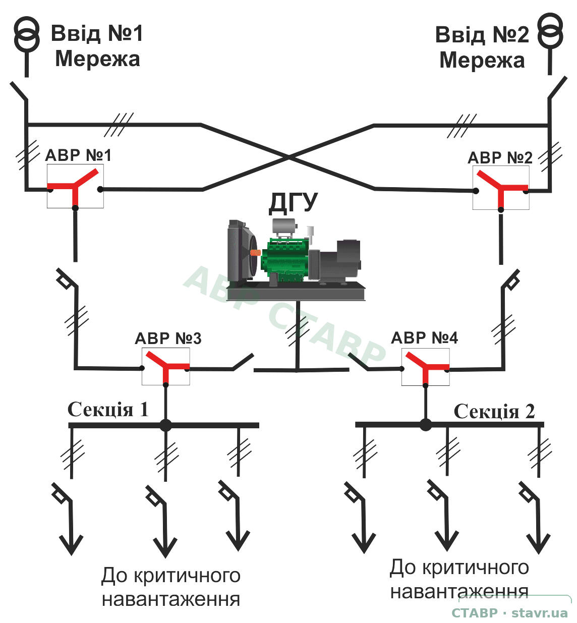
The shared generator set must support the load transferred to it under the design. Having two sections does not in itself mean a 2N architecture: path independence and UPS redundancy are assessed separately. The diagram illustrates the incoming-supply and transfer assembly, rather than a complete data centre power system.
Monitoring LV switchboards with ATS: status and standby readiness
Data centre operation depends not only on the presence of power, but also on readiness for the next transfer. An unavailable standby source, manual mode or bypass supply requires personnel attention even when IT equipment is operating normally.
| Monitored item | Information for personnel |
|---|---|
| Power sources | Voltage, frequency, phase status and compliance with set limits |
| Switching devices | Actual position, section power source and command confirmation |
| Operating modes | Automatic, manual, test and maintenance modes; bypass position |
| Standby readiness | Incoming-source availability, generator readiness and reasons for transfer inhibition |
| Load and faults | Current and power where metering is provided; protective-device operation and commands not executed |
The available functions depend on the equipment configuration. A transfer command and a confirmed switching-device position are different events. A time-stamped log and time synchronisation between the LV switchboard, UPS and generator controls allow the operating sequence to be reconstructed.
The design-specified signals are transmitted to BMS/DCIM through agreed protocols or dry contacts. Local controls and interlocks must perform their functions independently of supervisory communications.
Monitoring when all power sources fail
To retain monitoring during a total loss of power sources, the design should provide an autonomous backup power supply for the monitoring system.
For the specified autonomy period, the system retains incoming-source loss and restoration recording, device-position monitoring, event logging, local indication and alarm transmission.
Power must be provided for the entire required chain: controllers, signal acquisition devices, local indication, gateways, network switches and communications equipment. Otherwise, the controller may record the event without the control centre receiving it.
Autonomy is determined by the total-outage scenario and personnel response time. Backup-power faults, low charge or loss of readiness must generate warnings; autonomy is tested under the actual load.
Maintenance bypass and Dual ATS: types and operating procedures
During maintenance, two tasks must be addressed separately: maintaining power to the load and determining how power sources will be transferred once the main ATS has been taken out of service.
| Configurations | Supply with the ATS out of service | Power-source transfer | Operator involvement |
|---|---|---|---|
| Basic maintenance bypass | From the incoming supply specified by the circuit arrangement | Unavailable, or performed manually outside the ATS | Required |
| Source-selectable bypass | From one of the incoming supplies permitted by the circuit arrangement | Manual | Required |
| Dual ATS | Through the standby ATS | Automatic | Required to transfer between the main and standby ATS |
A maintenance bypass is not a second ATS. It provides a path around the main device and allows its isolation, but the basic configuration does not retain automatic source transfer.
In the STAVR solutions discussed, the operator transfers from the main ATS to bypass. Transfer of the load to the standby device in a Dual ATS arrangement is also initiated by the operator. The standby ATS then retains automatic transfer between the available power sources.
The standby ATS's ability to operate automatically must therefore not be confused with automatic transfer of the load from the main device to the standby device. The transfer and return procedures are defined in the operating instructions for the specific configuration.
The design must define which incoming supplies are available in maintenance mode, the equipment-isolation sequence, permitted operations and restoration of automatic operation. Bypass status and entry into maintenance mode are shown by the monitoring system.
CTTS can define the transfer mode of an individual device, but does not itself provide a bypass or redundancy for that device. The presence of a bypass likewise does not mean that Dual ATS is provided.
External maintenance bypass: basic configuration
The diagram shows the simplest external maintenance bypass arrangement: the load is supplied directly from the normal incoming supply, bypassing the ATS. A bypass with manual selection between the normal and standby sources can be provided where required by the project.
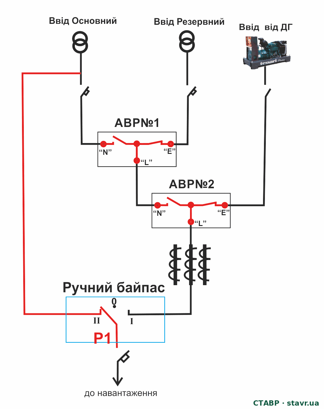
To maintain the ATS, moving P1 to bypass is accompanied by disconnecting the relevant incoming devices in accordance with the established procedure. Transfer to manual bypass causes a brief interruption of supply. During this interval, a healthy UPS located downstream of the transfer assembly, with sufficient stored energy, supports the critical load. The interruption duration depends on the device design and the transfer procedure.
In-phase transfer and uninterrupted transfer
In addition to the redundancy architecture, the method of transfer between sources matters for critical loads. In-phase transfer allows switching at a favourable instant and reduces transients. Where a supply interruption during planned transfer is unacceptable, CTTS is used: an ATS with closed transition and momentary parallel operation of synchronised sources.
Uninterrupted CTTS transfer is possible between two healthy, synchronised sources. If the active source suddenly fails, a UPS must maintain continuity of supply to the critical load until the standby source is connected.
In-phase transfer and CTTS do not replace N+1 or 2N redundancy and do not themselves determine a Tier level. They address a separate requirement: the necessary quality and continuity of transfer between sources.
More on the STAVR website
In-phase source transferOperating principle of the in-phase monitor in a high-speed ATSOpen the technical description →Uninterrupted ATS transfer — CTTSOperating principle of closed transitionOpen the technical description →Testing the system in its intended operating modes
The solution is tested against an agreed programme covering loss of each incoming supply, standby-source unavailability, loading after redistribution, interlocks and actual device positions, UPS interaction, return to the normal arrangement, maintenance operations and restoration of automatic operation.
Separate checks cover the conditions permitting and inhibiting closed transition, the effect of in-phase transfer on the particular UPS, event logging and message transmission. Backup power for monitoring and communications is tested under the actual load with all monitored power sources unavailable.
Scheduled checks and equipment diagnostics can be included in the ATS maintenance programme.
Selecting a data centre solution
| Project requirement | Appropriate solution |
|---|---|
| Two power sources; a brief interruption is acceptable | Open-transition ATS |
| Three power sources | Two cascaded ATS units |
| UPS battery use must be minimised | High-speed in-phase transfer; verification with the specific UPS |
| Uninterrupted transfer is required | CTTS / closed transition between two healthy power sources |
| ATS maintenance with the load remaining supplied is required | External maintenance bypass; allowance for the transfer interruption |
| Maintenance while retaining automatic standby transfer is required | Dual ATS; the operator transfers the load to the standby device |
| Standby-readiness monitoring is required | Monitoring, event logging and data transmission to BMS/DCIM |
The final solution is determined by the project, source characteristics, load structure, permissible operating modes and maintenance requirements.
Information required to design an LV switchboard with ATS
To define the configuration and verify system operation, the following must be provided or agreed:
- the single-line diagram;
- the number and types of power sources;
- rated voltage;
- design current;
- critical-load power and category;
- prospective short-circuit current;
- the presence and characteristics of generator sets, UPS systems or BESS;
- the permissible interruption duration;
- the need for in-phase or closed transition;
- the neutral-switching arrangement;
- maintenance bypass or Dual ATS requirements;
- monitoring requirements;
- the required supervisory-control protocols;
- the list of signals and commands.
Data centre power reliability depends not only on the number of standby sources, but on the entire system's ability to reliably deliver their energy to the load.
Send a single-line diagram or technical specification. STAVR specialists will check the redundancy scenarios, source loading after transfer and maintenance modes, and propose an LV switchboard configuration with ATS for your data centre.
STAVR LV switchboards with ATS are designed as critical components of data centre power systems, taking account of the target Tier level, anticipated failure scenarios, maintenance requirements and the facility's redundancy architecture.
STAVR diagrams illustrate redundancy principles and implementation examples. Equipment selection, ratings, protection and operating modes for a particular data centre are defined by the project.
Frequently asked questions
Does N+1 mean Tier III compliance?
No. N+1 describes redundant capacity. Tier III also requires the relevant equipment and distribution paths to be maintainable without shutting down the critical load.
How does 2N differ from two separate sections?
In a 2N arrangement, each independent path, A and B, supports 100% of the same critical load. Two sections may supply different groups without being able to back each other up.
Can the ATS remain a single point of failure?
Yes. If connection of the normal and standby sources depends on one non-redundant ATS, its failure can interrupt the corresponding circuit.
How does in-phase transfer differ from CTTS?
In-phase open transition includes a brief interruption. CTTS connects the incoming source first and momentarily parallels the two sources under permitted synchronism conditions.
What does uninterrupted transfer mean?
In this article, it means CTTS closed transition between two healthy power sources. It does not eliminate an interruption that has already occurred because the active source suddenly failed.
How does Dual ATS differ from a maintenance bypass?
In the solutions discussed, the operator transfers the load to the standby ATS, which then switches power sources automatically. A maintenance bypass provides a path around the main ATS.
Does a maintenance bypass provide automatic source transfer?
A basic manual bypass does not. It supplies the load from a specified incoming supply. A source-selectable bypass requires manual transfer.
Is installing two generators enough to achieve N+1?
Only if, after one fails, the other can supply the entire design load under the specified conditions. This provides redundant generator capacity; the ATS and other shared components must be assessed separately.
Need a solution for your data centre?
Send a single-line diagram or technical specification. STAVR will check redundancy scenarios, loading after transfer and maintenance modes, and propose an LV switchboard configuration with ATS.