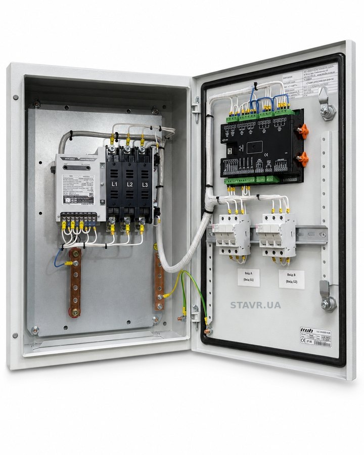
 200 A
Two-source 200 A ATS
A conventional utility–utility or utility–generator arrangement with mechanical interlocking, manual operation and a centre-off position.
ATS page
Industrial ATS and LV switchboards for critical facilities.
Switching mechanisms, complete LV switchboards with ATS, solutions for two and three power sources, no-break ATS, controllers, monitoring and Series WN technical specifications.
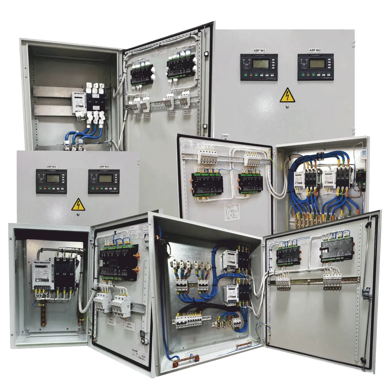
Series WN provides the power switching platform for two- and three-source ATS, complete LV switchboards, generator systems and no-break ATS for critical loads.
200 AA conventional utility–utility or utility–generator arrangement with mechanical interlocking, manual operation and a centre-off position.
ATS page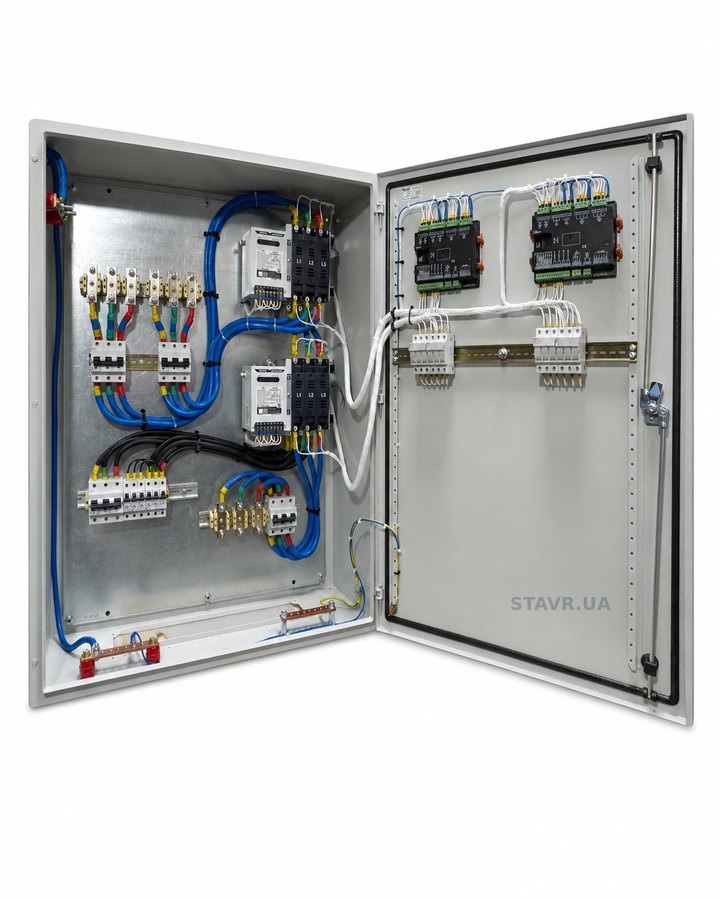 200 A
Utility–utility–generator or utility–generator 1–generator 2, with two coordinated switches and generator control.
Three-source diagrams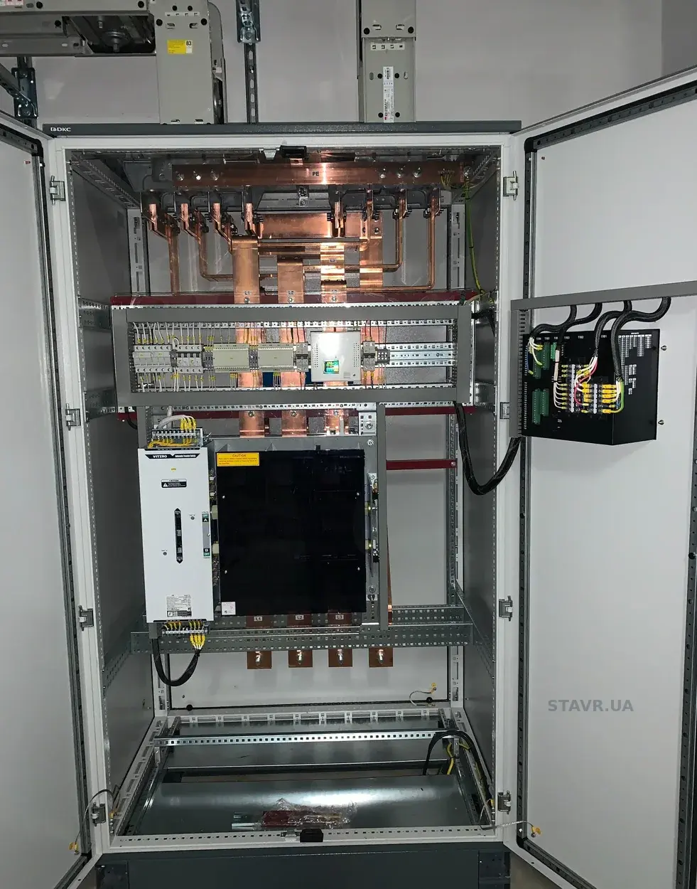 2500 A
Brief overlap of two live, synchronised sources using the make-before-break principle.
No-break transfer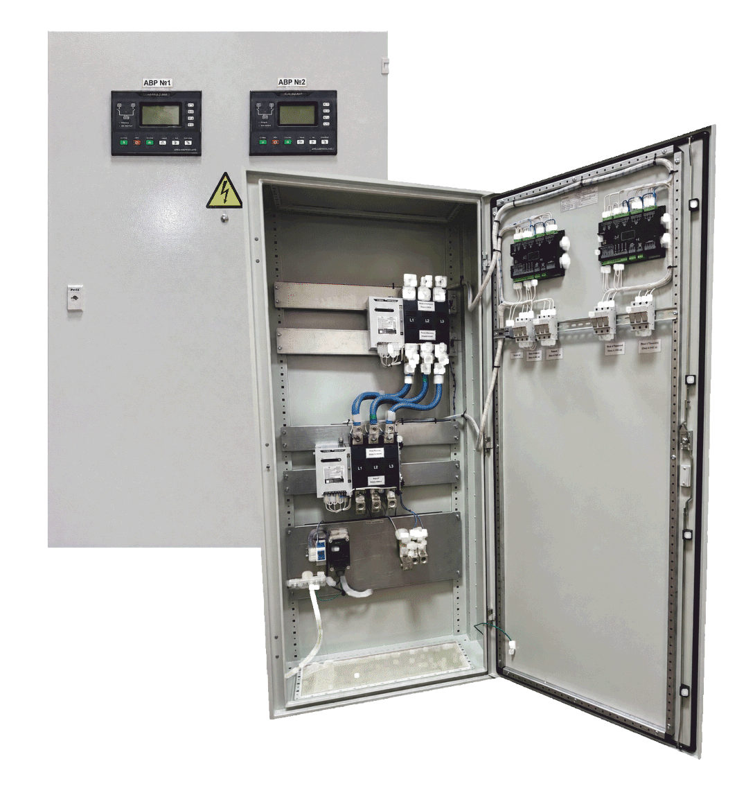 600 A
Utility–utility–generator or utility–generator 1–generator 2, with two coordinated switches and generator control.
Three-source diagramsThe diagram should show the sources and load, the sequence of power contact positions and the conditions under which transfer is permitted.
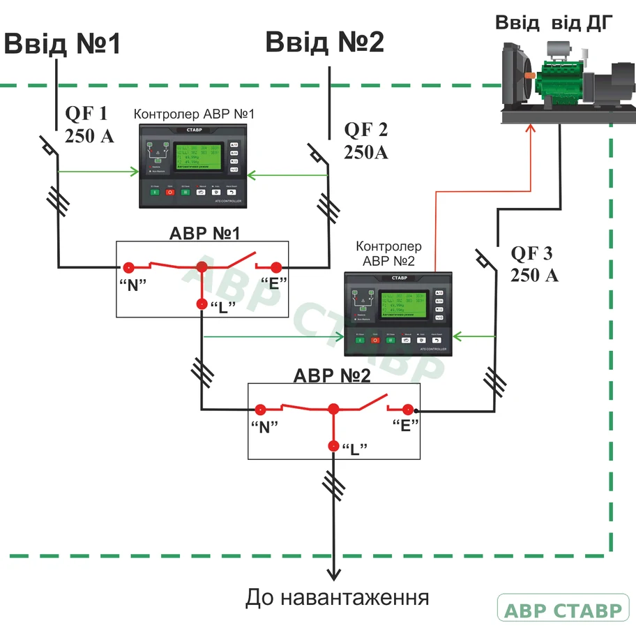
Typical utility–utility–generator architecture: two coordinated ATS units, position monitoring and a generator start/stop command.
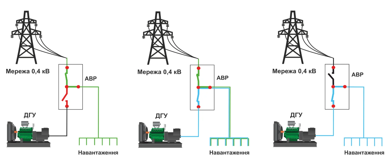
No-break transfer from utility to generator: the generator is started in advance and both sources have acceptable parameters. The controller does not synchronise the sources; it waits until the phase-angle, frequency and voltage differences fall within the set limits. Brief contact overlap then takes place and the load remains energised.
Fast operation. Few moving parts. Highly repeatable transfer performance.
The pulse-operated electromagnetic drive provides rapid, positive transfer between power sources without a prolonged motor-driven contact travel. The mechanical interlocking system prevents simultaneous connection of the normal and standby sources in standard ATS operation.
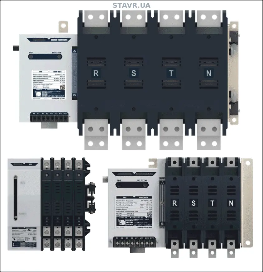
Solenoid-operated Series WN switches in different frame sizes. The specific version is determined by the rated current and number of poles.
The table shows typical catalogue configurations from 100 to 600 A. Cabinet, protection, busbar and short-circuit withstand parameters are confirmed separately for each project.
Rated voltage up to 600 V AC · 2, 3 or 4 poles
| Parameter | 100 A | 200 A | 400 A | 600 A |
|---|---|---|---|---|
| Rated operational voltage Ue | 600 V AC | 600 V AC | 600 V AC | 600 V AC |
| Rated insulation voltage Ui | 800 V AC | 800 V AC | 800 V AC | 800 V AC |
| Rated impulse withstand voltage Uimp | 8 kV | 8 kV | 8 kV | 8 kV |
| Rated short-time withstand current Icw, 1 s | 5 kA | 10 kA | 12 kA | 15 kA |
| Utilisation category | AC-33B | AC-33B | AC-33B | AC-33B |
| Electrical endurance | 5,000 cycles | 5,000 cycles | 5,000 cycles | 5,000 cycles |
| Mechanical endurance | 10,000 cycles | 10,000 cycles | 10,000 cycles | 10,000 cycles |
| Transfer time | ≤55 ms | ≤55 ms | ≤55 ms | ≤80 ms |
| Typical cabinet, H×W×D | 600×400×250 | 600×400×250 | 800×600×250 | 1200×800×300 |
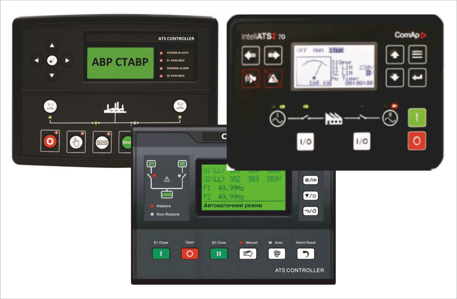
Examples of controllers with different functionality used in STAVR ATS assemblies. The specific model is determined by the circuit, operating sequence and supervisory monitoring requirements.
Controller selection depends on the number of sources, generator control requirements, transfer logic, measurements and integration with supervisory systems, rather than the appearance of the front panel.
From a basic complete ATS assembly to an LV switchboard with metering, SPD, bypass, neutral switching and remote monitoring.
The final ATS configuration is determined by the design current, short-circuit currents, load characteristics, number of sources, neutral arrangement and continuity requirements. See also the articles on DSTU EN 60947-6-1, AC-33B and neutral switching.
Send a single-line diagram or the basic parameters: current, voltage, sources, number of incoming supplies and poles, bypass, SPD and supervisory monitoring requirements.